90
3. Motor, Abnormalities in Actuator System
The drive circuit of a motor & actuator consists of the three ICs IC601(R2S30202FP). The work of each IC is
as follows.
(1) IC601(R2S30202FP) : 7ch driver
Spindle motor driver: 180° audio drive Type, an analog input, a PWM drive, a Vm=12V.
Stepping motor driver X2: analog input, a PWM drive (differential), a Vm=12V
Loading motor driver: Input/Output PWM drive, Vm=5V.
Focus actuator driver: analog input / output (differential), a Vm=5V
Tracking actuator driver: analog input / output (differential), Vm=5V
Tilt actuator driver : analog input/output (differential), Vm=5V.
A motor & actuator and its correspondence pin
A control mode setup by the control terminal
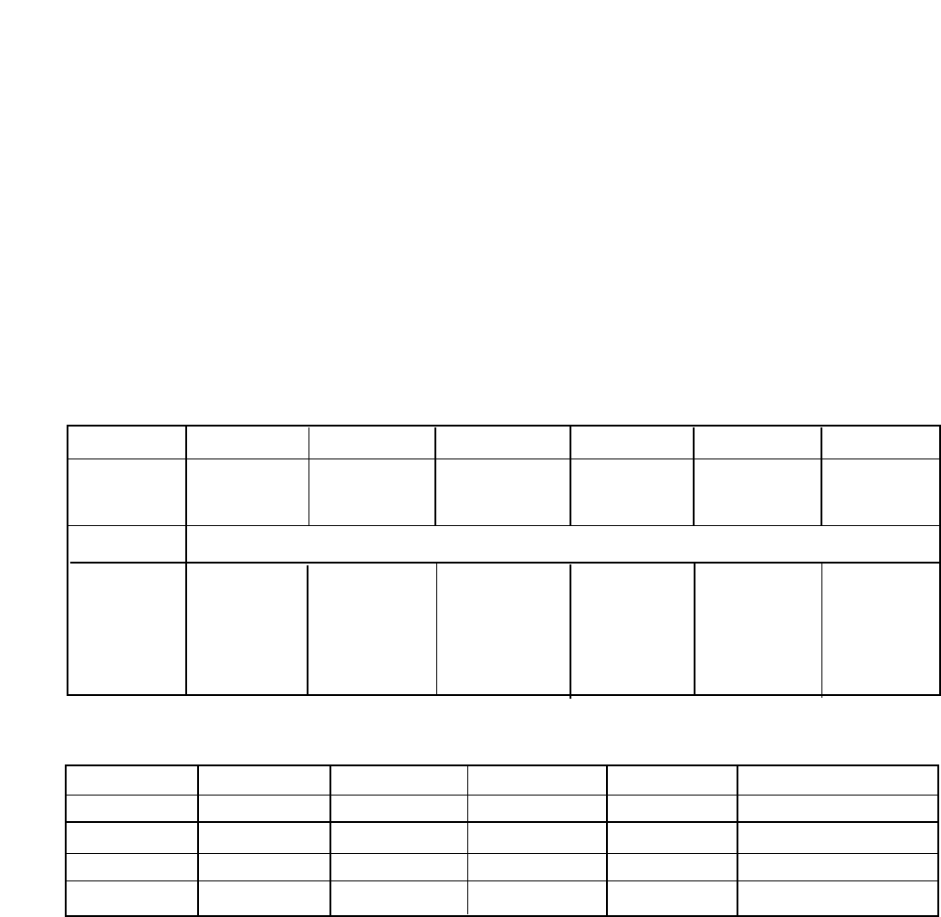
Signal/CH SPDL-MT STEP-MT Load-MT Focus-ACT Track-ACT Tilt-ACT
Input (1)SPIN (2)SL1IN (41)LOIN (40)FOIN (39)TOIN (38)TLIN
(3)SL2IN
Reference (42)REF 1.65V
Output (12)U (6)SL2+ (27)LO+ (34)FO+ (31)TO+ (36)TL+
(13)V (8)SL2- (28)LO- (35)FO- (30)TO- (37)TL-
(14)W (9)SL1+
(10)SL1-
EN1(20) EN2(21) SPDL SLED Load Focus/Track/Tilt
Low Low off off off off
Low High off on on off
High Low on on off on
High High on on off on


