


27
EXTERNAL CONTROL DEVICE SETUP
ENGENGLISH
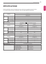
EXTERNAL CONTROL DEVICE SETUP
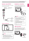
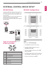
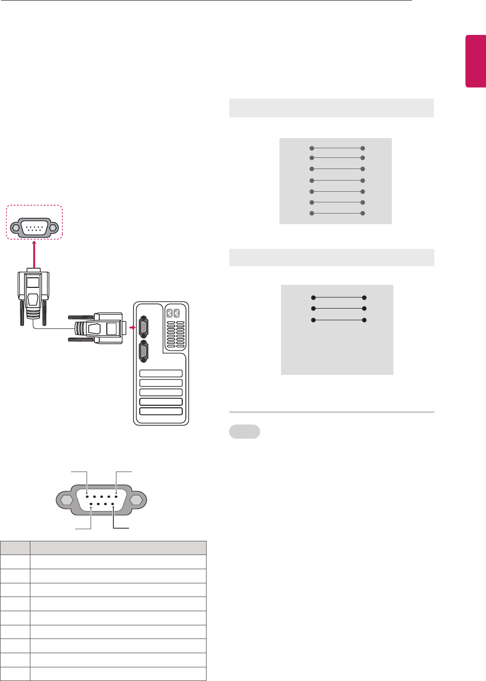
RS-232C Setup
Connect the RS-232C (serial port) input jack to an
external control device (such as a computer or an
A/V control system) to control the product’s func-
tions externally.
Connect the serial port of the control device to the
RS-232C jack on the product back panel.
Note: RS-232C connection cables are not supplied
with the product.
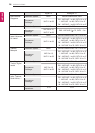
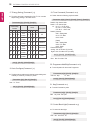
Type of connector;
D-Sub 9-Pin Male
No. Pin name
1 3.5V
2 RXD (Receive data)
3 TXD (Transmit data)
4 IR OUT from TV
5 GND
6 No Connection
7 +5V Power out
8 No Connection
9 +12V Power out
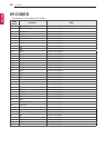
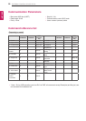
RS-232C Congurations
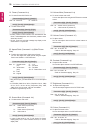
Set ID
Set ID number. "Real Data Mapping".
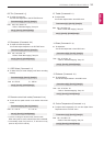
1
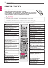
Press Home to access the main menus.
2 Press the Navigation buttons to scroll to
OPTION and press OK.
3 Press the Navigation buttons to scroll to SET
ID and press OK.
4 Scroll left or right to select a set ID number and
select CLOSE. The adjustment range is 1-99.
5 When you are finished, press EXIT.
1 2
EXTERNAL
SPEAKER OUT
RGB IN (PC)
R
ANTENNA/
CABLE IN
DC IN
RS-232C IN
(CONTROL & SERVICE)
R
RS-232C IN
(CONTROL & SERVICE)
(RGB/DVI)
RS-232C IN
(CONTROL & SERVICE)
ANTENNA
IN
RGB IN (PC)
1
DC IN
2
AV
(RGB)
AUDIO IN
5
6 9
1
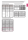
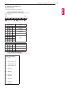
7-Wire Configurations
(
Standard RS-232C cable
)
PC TV
RXD 2 3 TXD
TXD 3 2 RXD
GND 5 5 GND
DTR 4 6 DSR
DSR 6 4 DTR
RTS 7 8 CTS
CTS 8 7 RTS
D-Sub 9 D-Sub 9
3-Wire Configurations(Not standard)
PC TV
RXD 2 3 TXD
TXD 3 2 RXD
GND 5 5 GND
DTR 4 6 DTR
DSR 6 4 DSR
RTS 7 7 RTS
CTS 8 8 CTS
D-Sub 9 D-Sub 9