


6
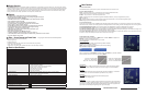
Operational Setup
1. Unpack the V-R84DP-SD and accompanying V-PS12-5V-1 power supply. Physically inspect for any damage that may have
occurred during shipping. Should there be any damage, immediately contact Marshall Electronics at 800-800-6608.
If you are not located within the continental United States call +1 310-333-0606.
2. After inspection, install in your desired location of a standard EIA 19-inch equipment rack.
Adequate ventilation is required when installed to prevent possible damage to the V-R84DP-SD internal components.
3. Connect required cables for signal input and output. Please note that power must be applied to the V-R84DP-SD for all outputs
to be activated. All BNC connectors should be rated for 75Ω.
4. Plug the V-PS12-5V-1 power supply into the A.C. source
5. Attach twist lock power connection from V-PS12-5V-1 power supply to the back of the unit.
6. Turn on each of the V-R84DP-SD screens by depressing the power switch located on the front of the unit for each screen.
7
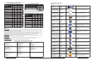
Connectors
* SDI Inputs comply to SMPTE-259M,SDI-270Mbs
* Component Inputs comply to SMPTE274M, 294M, 295M, 296M
* Composite Video Inputs comply to SMPTE-170M
* Tally lamps active when connected to ground
* Battery and External Power can not be used simultaneously
S-Video In
4 Pin Din (Female)
Pin1 - GND
Pin2 - GND
Pin3 - Yin
Pin4 - Cin
S-Video Out
4 Pin Din (Female)
Pin1 - GND
Pin2 - GND
Pin3 - Yout
Pin4 - Cout
12 VDC from
V-PS12-5V-1 power supply
Pin 1 - Neg
Pin 2 - Pos
VGA/XGA Connector
PIN# SIGNAL PIN# SIGNAL
1 RED 9 NC
2 GREEN 10 NC
3 BLUE 11 NC
4 NC 12 NC
5 GND 13 HSYNC
6 RED SHIELD 14 VSYNC
7 GREEN SHIELD 15 NC
8 BLUE SHIELD
DVI-I Connector
Pin#
Signal
Pin#
Signal
1 T.M.D.S DATA 2- 16 HOT PLUG DETECT
2 T.M.D.S DATA 2+ 17 T.M.D.S DATA 0-
3 T.M.D.S DATA 2/4
SHIELD
18 T.M.D.S DATA 0+
4 T.M.D.S DATA 4- 19 T.M.D.S DATA 0/5
SHIELD
5 T.M.D.S DATA 4+ 20 T.M.D.S DATA 5-
6 DDC CLOCK 21 T.M.D.S DATA 5+
7 DDC DATA 22 T.M.D.S CLOCK
SHIELD
8 ANALOG VERT. SYNC 23 T.M.D.S CLOCK+
9 T.M.D.S DATA 1- 24 T.M.D.S CLOCK-
10 T.M.D.S DATA 1+
11 T.M.D.S DATA 1/3
SHIELD
C1 ANALOG RED
12 T.M.D.S DATA 3- C2 ANALOG GREEN
13 T.M.D.S DATA 3+ C3 ANALOG BLUE
14 +5V POWER C4 ANALOG HORZ SYNC
15 GND C5 ANALOG GROUND
Dimensions 10.25”w x 7” h x 2.5” d (260.4mm x 215.9mm x 38.1mm)
V-R84DP-SD Weight 4 lbs (1.8 kg)
V-PS12-5V-1 Power Supply Weight 1 lbs (0.45kg)
5
Mechanical Specifications
3
6
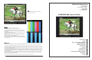
V-R82DP-HD Users Guide
Marshall Electronics
Pin1-Yel
Pin2-Red
Pin3-Grn
Pin4-
Pin5-Gnd
Pin6-
Pin7-
Pin9-
Pin10-
Pin11-
Pin12-
Pin13-
Pin14-
Pin15-Gnd
Tally IN
DB-15 Female
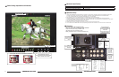
Dry Erase
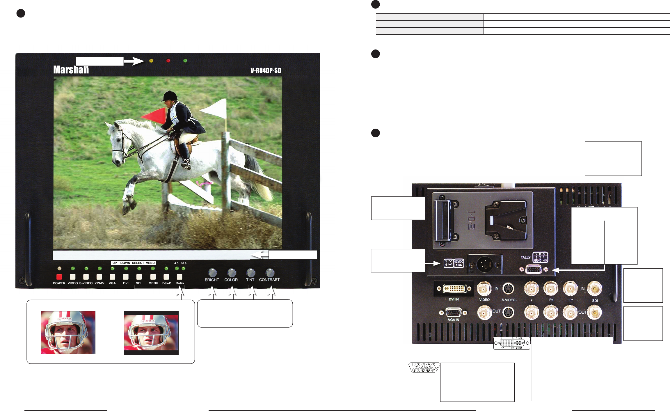
Screen aspect ratio switch 4:3 or 16:9 selector and indicators
4:3 Aspect 16:9 Aspect
10
Switch Settings, Adjustments and Indicators
Tally Lamps
V-R84DP-SD Users Guide
Marshall Electronics
Active Outputs require
power to be applied
All input signals appear as
output signal
Analog output signals are
buffered and amplifi ed
V-Mount Battery Adapter
See Optional Accessory
section for a selection of
batteries
Image Adjustment Controls
Note: Tint only functions when NTSC
Video or S-Video are selected