


6 7
Controls/Functions
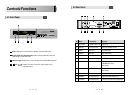
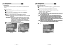
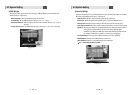
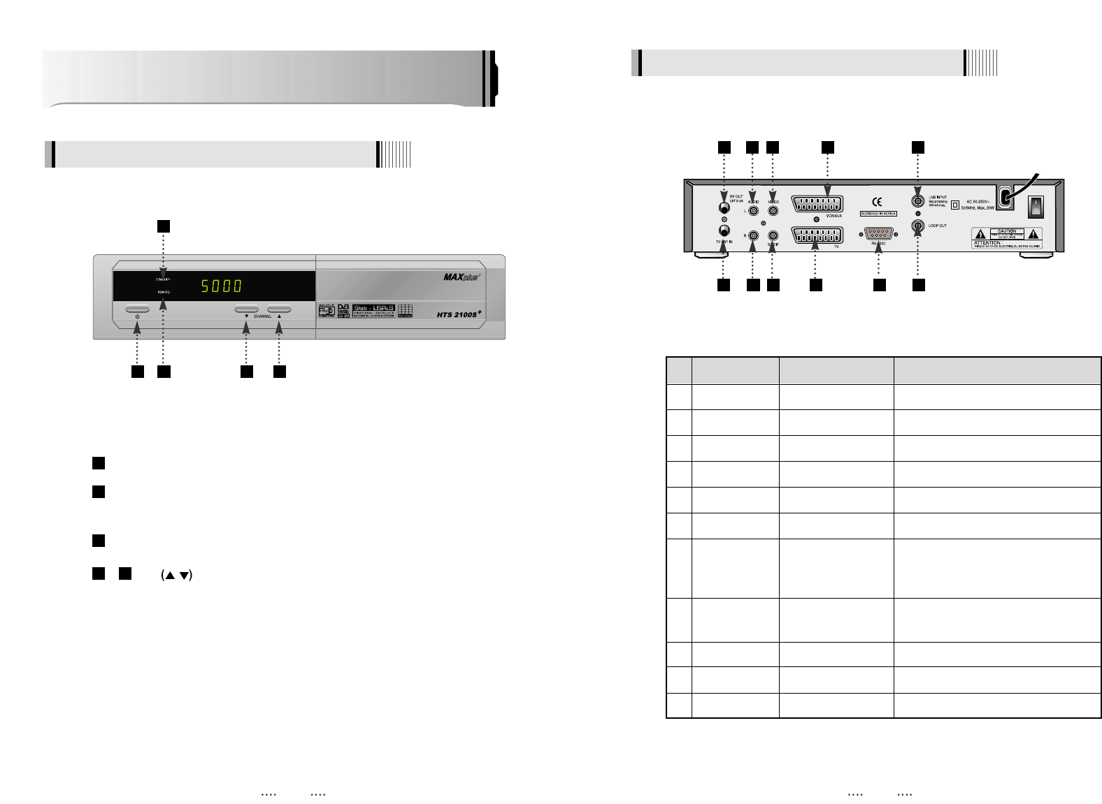
4.1 Front Panel
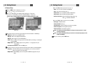
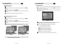
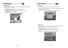
4.2 Rear Panel
Power : Switches the receiver between ‘Standby’ and ‘Power ON’ modes.
Standby/Power on Indications Lamp : Flashes red light in ‘Standby’ mode and
shows no light in ‘Power ON’ mode.
Indication Light : Flashes when a key on the Remote Control Unit (RCU) is pressed.
- CH.
/ : To switch channels or change the cursor position on the
application screen.
54
3
2
1
2
1 3 4 5
10
1 3 5 7
9
11
2 4 6 8
No. Name Connector Function
1 RF OUT UHF 21-69 IEC 169-2 male Output to TV
2 TV ANT IN IEC 169-2 female Input from terrestrial antenna
3 AUDIO L RCA cinch Left audio output
4 AUDIO R RCA cinch Right audio output
5 VIDEO RCA cinch Composite video output
6 S/PDIF RCA cinch Digital audio output
7 VCR/AUX SCART SCART CVBS Video Output
CVBS, RGB Video Input
Audio Output
8 TV SCART SCART CVBS, RGB Video Output
Audio Output
9 RS-232C DB-9 Low speed serial port
10 LNB INPUT IEC 169-24 female IF input from LNB to digital tuner
11 LOOP OUT IEC 169-24 female IF loop-through output from digital tuner