


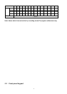
alarm triggered, COM disconnect with NC, and connect with NO.
PIN 8. EXTERNAL ALARM NO
Under normal operation COM connect with NC and disconnect with NO. But when
Alarm triggered, COM disconnect with NC, and connect with NO.
PIN 9. GND
GROUND
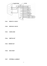
PIN 10. RS485-B
DVR can be controlled remotely by an external device or control system, such as a
control keyboard, using RS485 serial communications signals.
PIN 11. RS485-A
DVR can be controlled remotely by an external device or control system, such as a
control keyboard, using RS485 serial communications signals.
PIN 12. DISK FULL
When HDD is full, it sends a signal to trigger next DVR record mode, if you install
another DVR. Under normal operation, the signal remains “High”. But when disk full,
DVR will send the “Low” signal.
PIN 13. ALARM RESET
To connect wire from ALARM RESET ( PIN 13 ) to GND ( PIN 9 ) connector, it can
disable ALARM. An external signal to ALARM RESET ( PIN 13 ) can be used to
reset both ALARM OUTPUT signal and DVR’s internal buzzer. When alarm has
been triggered, signal becomes “Low”, and it will stop all alarm activities. Under
normal operation, signal remains “High”.
PIN 14. ALARM INPUT
To connect wire from ALARM INPUT ( PIN 14 ) to GND ( PIN 9 ) connector, DVR
will start recording and buzzer will be on. When alarm has been triggered, signal
becomes “Low”, and it will stop all alarm activities. Under normal operation, signal
remains “High”.
PIN 15. COM
Under normal operation COM connect with NC and disconnect with NO. But when
alarm triggered, COM disconnect with NC, and connect with NO.
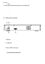
4. Power input
Connect to power cord (standard package attached).
3.4 Menu setup
14