


2
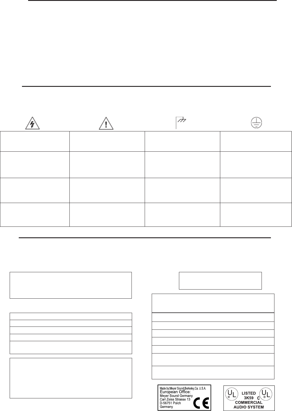
Pour indiquer les risques
résultant de tensions
dangereuses
Zu die gefahren von
gefährliche spanning zeigen
Important operating
instructions
Pour indequer important
instructions
Zu wichtige betriebs-
anweisung und unter-
haltsanweisung zeigen
Frame or chassis
Masse, châssis
Rahmen oder chassis
Protective earth ground
Terre de protection
Die schutzerde
Para indicar azares provengo
de peligroso voltajes
Para indicar importante
funcionar y mantenimiento
instrucciones
Armadura o chassis Tierra proteccionista
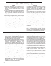
These symbols indicate important safety or operating features in this booklet and on the chassis.
Dangerous voltages:
risk of electric shock
Symbols Used
According to ISO/IEC Guide and EN 45014
Declaration of Conformity
declares that the product:The Manufacturer:
Product Name: SB-1
Product Options: All
Name: Meyer Sound Laboratories
Address: 2832 San Pablo Avenue
Berkeley, California 94702-2204, USA
conforms to the following Product Specifications:
Safety: EN 60065: 1994
EMC: EN 55022: 1987 - Class A
IEC 801-2: 1984 - 8 kV
IEC 801-3: 1984 - 3 V/m
IEC 801-4: 1984 - 0.5 kV Signal Lines,
1.0 kV Power Lines
The product herewith complies with the requirements
of the Low Voltage Directive 73/23/EEC and the EMC
Directive 89/336/EEC.
Office of Quality Manager
Berkeley, California USA
October 1, 1995
Shock: 30 g 11 msec half-sine
on each of 6 sides
Vibration: 10 – 55 Hz (0.010 m
peak-to-peak excursion)
Operating temperature: 0° C to +45° C
Nonoperating temp: < –40° C or > +75° C
Humidity: to 95% at 35°C
Operating altitude: to 4600 m (15,000 ft)
Nonoperating altitude: to 6300 m (25,000 ft)
Environmental Specifications for
Meyer Sound Electronics Products
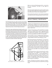
Contents
AC Power .................................................. 3
Audio Input ................................................. 4
AC Troubleshooting ...................................... 5
Limiting and Protection Circuitry ..................... 5
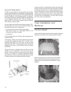
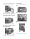
Fans and Cooling Systems ............................. 7
Yoke Installation and Removal ........................ 6
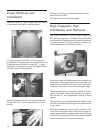
Cover Removal and Installation ........................ 8
High Frequency Pod Installation and Removal ...... 8
Driver Phase Verification ................................ 9
Safety Summary ......................................... 10
Controls and Connectors .............................. 11
Dimensions ................................................ 11