


9
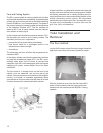
While keeping a firm grip on the pod insert one of the legs
into a c-bracket so that the holes in the legs are aligned with
the holes in the c-bracket. Then insert a pin through the
holes while pressing down on its button head. When the
first pin is in position attach the leg opposite to the first one.
Repeat this process until all four legs are attached.
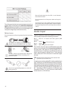
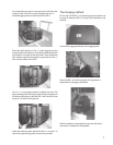
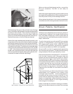
When all four legs are attached and locked in position, use
a tape measure to measure the distance between the edge
pod facing the dish and the most inner surface of the dish.
Lay the tape along the side of the pod so that it is not curved
in its decent into the dish. The distance from the dish edge
of the pod to the surface of the dish must be 13.25” inches
+/- 0.25” . If the distance does not match this specification
the SB-1 will not operate properly, remove the pod from the
dish and reposition the legs by rotating the leg shaft in 180°
increments to extend or shorten their length.
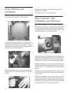
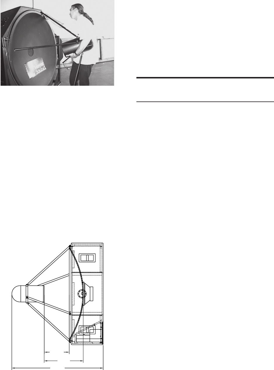
48.50
13.25
20.75
When you have verified the pod position, connect the
EP-4 pin connectors. The SB-1 is now ready for
operation.
When removing the high frequency pod be careful not to let
the weight of the pod bend any of the brackets as this will
skew the position of the pod and damage the SB-1.
When placing the pod back in the internal compartment
remember to position the legs between the foam inserts.
Driver Polarity Verification
All Meyer Sound Speakers leave the factory wired for
proper polarity. However, if you suspect that the wiring
may have been altered due to service performed by
anyone other than certified Meyer personnel follow the
steps listed below.
To verify driver polarity you will need a EP-4 pin polarity
reverser, a noise generator, and a frequency specific
SPL measurement system. While a SIM-2201 would
be ideal for this application, any analyzer capable of
accurate measurements at 500 Hz is acceptable.
Set up the SB-1 so that it is powered and reproducing
the noise from the generator. The dish should be facing
straight ahead so that the pod assembly is level.
Place the measurement microphone 75° off-axis and 5’
from the high frequency pod. Generate noise and
measure the sound pressure level at 500 Hz. Without
altering the level of signal, insert the EP-4 pin polarity-
reverser between the EP-4 pin connectors. Measure the
sound pressure level at 500 Hz. If second measurement
is greater than the first, then the drivers are wired for
proper polarity. If the first measurement is greater than
the first either the high driver is miswired in the high
frequency pod or the MS-12 in the center of the dish is
miswired.
The measurement you have just performed is a lobe
measurement, as 75 degrees is far outside of the
coverage angle of the SB-1. A lobe measurement is
necessary as the primary function of the MS-12 is to
cancel the low frequencies outside of the primary 10
degree coverage angle. When the phase of one of the
drivers is reversed the MS-12 is no longer canceling
lobe energy but increasing it.
Keep in mind that this increase in energy is not desir-
able since the affected space is outside of the coverage
angle.
High Frequency Tranducer Pod Setup Dimensions