


Installation Guide: MIL-140TRM
6 3
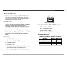
Indicators
There are four LEDs, including:
•
TP/ACT
: Receiving packets from the 10BASE-T port
•
TP/LINK
: There is an active connection on the
10BASE-T port
•
FX/LINK
: There is an active connection on the
10BASE-FL port
•
FX/ACT
: Receiving packets from the 10BASE-FL port
Specifications
RJ-45: MDI
• Pin 1 = Transmit Data +
• Pin 2 = Transmit Data -
• Pin 3 = Receive Data +
• Pin 6 = Receive Data -
RJ-45: MDI-X
• Pin 1 = Receive Data +
• Pin 2 = Receive Data -
• Pin 3 = Transmit Data +
• Pin 6 = Transmit Data -
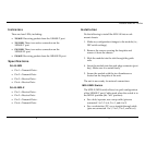
Installation
Do the following to install the MIL-140 into a rack
mount chassis:
1. Make any configuration changes to the module (i.e.,
DIP switch settings).
2. Remove the screws securing the faceplate and
remove it from the chassis.
3. Slide the module into the slot through the guide
rails.
4. Insert the module into the card-edge connector (port
bay). Make sure it is seated firmly.
5. Secure the module with the two thumbscrews
located on the faceplate of the unit.
The unit is now ready for network connections.
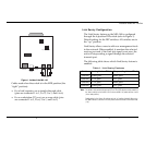
MDI-X/MDI Switch
The MDI-X/MDI switch allows for quick configuration
of the 10BASE-T port. Cables used when the switch is in
the MDI-X position (the “left” position):
• For a hub/repeater, use a swap cable (pins are
connected 1 to 3, 2 to 6, 3 to 1, and 6 to 2)
• For a workstation/PC, use a straight-through cable
(pins are connected 1 to 1, 2 to 2, 3 to 3, and 6 to 6)