


Installation Guide: MIL-140TRM
4 5
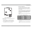
Figure 1. Inside of the MIL-140
Cables used when the switch is in the MDI position (the
“right” position):
• For a hub/repeater, use a straight-through cable
(pins are connected 1 to 1, 2 to 2, 3 to 3, and 6 to 6)
• For a workstation/PC port, use a swap cable (pins
are connected 1 to 3, 2 to 6, 3 to 1, and 6 to 2)
Link Sentry Configuration
The Link Sentry feature on the MIL-140 is configured
through the 4-position DIP switch (refer to Figure 1).
Default setting for the DIP switches: All switches are in
the “up” position.
Link Sentry allows users to add new management tools
to the network. When enabled, it monitors the selected
receiver port and, if the Link test signal is not seen, the
unit will stop sending a signal through the selected
transmit port.
The following table shows which Link Sentry feature is
enabled:
Note:
For two MIL-140s used back-to-back and UTP-to-UTP, all DIP switches must be enabled (in
the “down” position) on the first MIL-140. On the second MIL-140, enable switches 1 and 4
(in the “down position).
Default setting for Link Sentry: All switches set in the “up” position (disabled). When using
the SNMP module to control the Link Sentry feature, leave the switches in the default mode
(“up”).
MDI-X/MDI
Switch
RJ-45 Female
Connector
ST-Type
Connectors
4
3
2
1
LEDs
(4 total)
4-pin DIP Switch
Table 1. Link Sentry Features
Switch Losing Link on RX of Stop sending Link on TX of
1 (down) Fiber port Fiber port
2 (down) UTP port UTP port
3 (down) UTP port Fiber port
4 (down) Fiber port UTP port