FX Series Programmable Controllers Points Of Technique 10
10-17
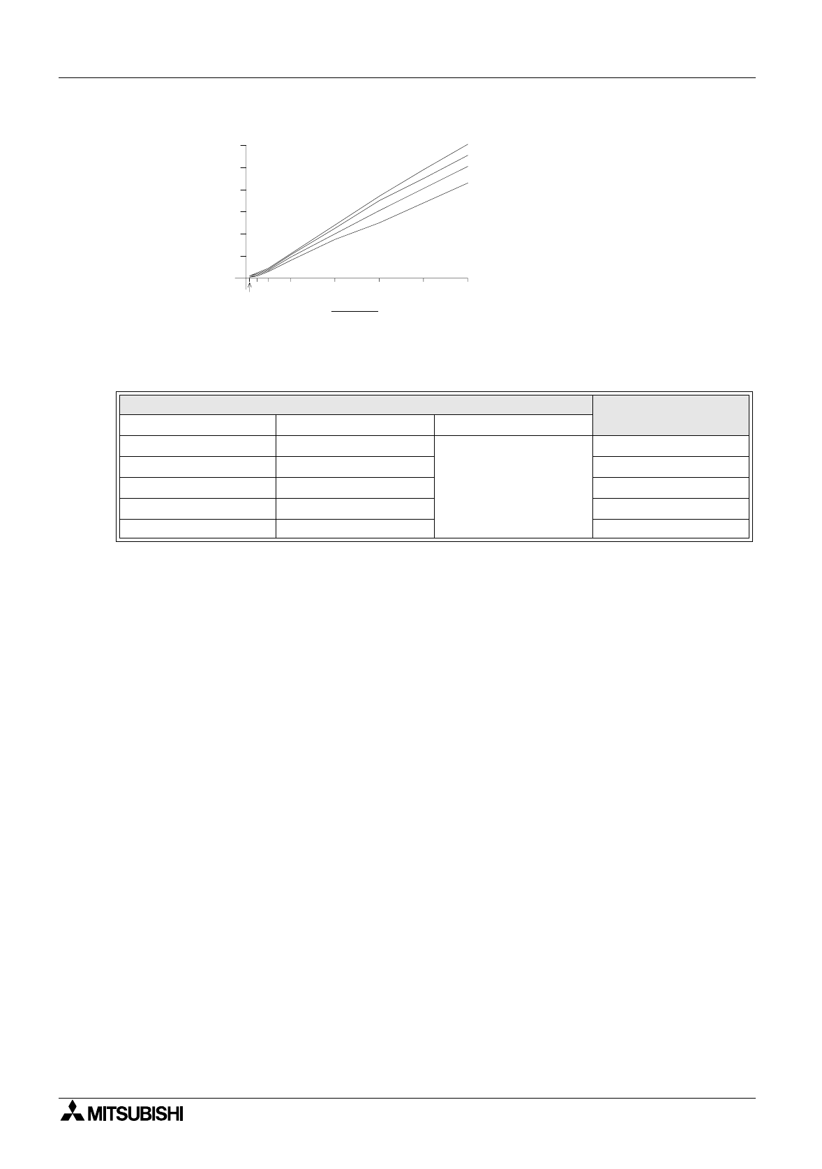
The duration of the T
0
, time base also affects the ripple volta
g
e. This can be clearl
y
seen in the
next set of test data:
The behavior of the Sink switched circuit detailed above will be similar to that of the Source
switched circuit detailed earlier.
PWM parameter setting
Measured ripple
voltage
tT
0
t / T
0
100 200
0.5
1.27V
50 100 668mV
25 50 350mV
10 20 154mV
510 82mV
20 3010
52.5
1.0
40 50
t
2.0
4.0
6.0
8.0
10.0
12.0
e (volts)
L1
L2
L3
L4
Tested load impedance
(e.g. inverter impedance)
L1 - 100 k
L2 - 10 k
L3 - 4.7 k
L4 - 2.2 k


