


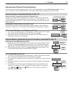
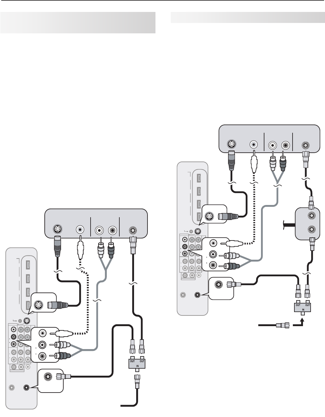
3. TV Connections 25
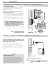
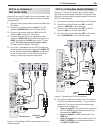
VCR to an Antenna or
Wall Outlet Cable
Required: Two-way RF splitter, two coaxial cables, right
and left analog audio cables, either S-video or compos-
ite video cable.
Connect the incoming cable or antenna to
1. IN
on the
RF splitter.
Connect one coaxial cable from
2. OUT
on the RF
splitter to
ANTENNA IN
on the VCR back panel.
Connect one coaxial cable from
3. OUT
on the RF
splitter to
ANT 1
on the TV main panel.
Connect either an S-Video or composite video
4.
cable from
VIDEO OUT
on the VCR back panel to a
VIDEO
composite or
S-VIDEO
jack on the TV main
panel. Connect only one type of video cable;
S-Video is recommended, if available.
To use the TV speakers with the VCR, connect left
5.
(white) and right (red) audio cables from
AUDIO OUT
on the VCR to the associated
AUDIO L
and
R
jacks
on the TV main panel. If your VCR is mono (non-
stereo), connect only the white (left) cable.
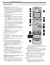
HDMI
4
3
2
1
IR-
Output / External
Controller Input
S-VIDEO
VIDEO
AUDIO
L
R
INPUT3
INPUT2 INPUT1
L
R
AVR AUDIO
OUTPUT
AUDIO
L
R
Pb
Y
Y / VIDEO
Pr
ANT2/AUX
ANT1/MAIN
DIGITAL
AUDIO
OUTPUT
NetCommand
) i 0 8 0 1 / p 0 2 7 / p 0 8 4 / i 0 8 4 (
AUDIO
R
DVI/PC
L
AUDIO
L
R
S-VIDEO
S-VIDEO
VIDEO
AUDIO
L
R
VIDEO
ANT1/MAIN
ANT1/MAIN
S-VIDEO
OUT
VIDEO
OUT
L R
AUDIO OUT ANTENNA
IN
VCR
TV main panel
2.
2.
1.
4.
4.
5.
5.
3.
3.
Incoming
cable
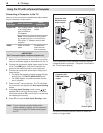
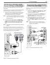
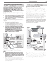
VCR to a Cable Box (Audio & Video)
Required: Two-way RF splitter, three coaxial cables,
right and left audio cables, S-Video or composite video
cable, plus video and audio cables required to connect
the TV to the cable box.
Connect the incoming cable to
1. IN
on the RF splitter.
Connect one coaxial cable from
2. OUT
on the RF
splitter to
CABLE IN
on the cable box.
Connect one coaxial cable from
3. OUT
on the RF
splitter to
ANT 1
on the TV main panel.
Connect one coaxial cable from
4. OUT
on the cable
box to
ANTENNA IN
on the VCR back panel.
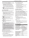
OUT
IN
HDMI
4
3
2
1
IR-
Output / External
Controller Input
S-VIDEO
VIDEO
AUDIO
L
R
INPUT3
INPUT2 INPUT1
L
R
AVR AUDIO
OUTPUT
AUDIO
L
R
Pb
Y
Y / VIDEO
Pr
ANT2/AUX
ANT1/MAIN
DIGITAL
AUDIO
OUTPUT
NetCommand
) i 0 8 0 1 / p 0 2 7 / p 0 8 4 / i 0 8 4 (
AUDIO
R
DVI/PC
L
AUDIO
L
R
S-VIDEO
S-VIDEO
VIDEO
AUDIO
L
R
VIDEO
ANT1/MAIN
ANT1/MAIN
S-VIDEO
OUT
VIDEO
OUT
L R
AUDIO OUT ANTENNA
IN
6.
6.
7.
7.
VCR
TV
main
panel
2.
2.
1.
4.
3.
3.
Incoming
cable
4.
5.
Audio and
video from
cable box
to TV
Cable
box
Figure 9. Connecting a VCR to a cable box
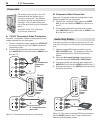
Connect the cable box outputs to the TV as shown
5.
in one of the options listed below. This connection
allows the TV to receive the best available signal
directly from the cable box.
• Figure1,page22: Component video output to
the TV’s
Y Pb Pr
jacks; analog stereo audio to
the associated
AUDIO
jacks.
• Figure 2, page 22: HDMI output to the TV’s
HDMI
jack.
• Figure 4, page 23: S-Video output to the TV’s
INPUT 3
S-VIDEO
jack; analog stereo audio to
the
INPUT 3
AUDIO
jacks.
Figure 8. Connecting a VCR to allow recording from an
antenna source.