


3. TV Connections 23
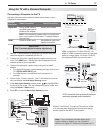
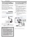
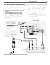
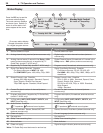
Required: Two-way RF splitter, 3 coaxial cables, right
and left analog audio cables, either S-video or video
cable.
1. Connect the incoming cable or antenna to
IN
on the
RF splitter.
2. Connect one coaxial cable from
OUT
on the RF
splitter to
ANTENNA IN
on the VCR back panel.
3. Connect one coaxial cable from
OUT
on the RF
splitter to
ANT 1/MAIN
on the TV back panel #2.
This allows you to use TV Guide Daily (model
LT-40134 only).
Figure 9. Connecting a VCR to an Antenna or Wall Outlet Cable
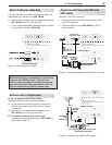
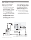
4. To use the TV speakers with the VCR, connect left
(white) and right (red) audio cables from
AUDIO
OUT
on the VCR to
INPUT AUDIO L (MONO)
and
AUDIO R
on the TV back panel #1. If your VCR is
mono (non-stereo), connect only the white (left)
cable.
5. Connect either an S-Video or composite video
cable from
VIDEO OUT
on the VCR back panel to
INPUT VIDEO
or
S-VIDEO
on the TV back panel #1.
Connect only one type of video cable; S-Video is
recommended, if available.
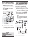
VCR to an Antenna or Wall Outlet Cable
065165
*3&.*55&3
%*(*5"-
"6%*0
*/165
47*%&0
7*%&0
-
.0/0
3
3
3
:
1C
1S
3
-
-
.0/0
-
.0/0
"73065
%7**/
"6%*0
$0.10/&/5
*/1654
"73
"6%*0065165
1$%7*
"6%*0*/165
$0.10/&/5
*/1654
JQQJ
#"$,*/1651"/&-
CFMPXMBCFMXJUIJOSFDFTTFEBSFBBUUPQ
065165
*3&.*55&3
%*(*5"-
"6%*0
"/5."*/
065
*/
*/
*/
3
-.0/0
"6%*0
065
*/
3
-
065
47*%&0
"/5&//"
065
7*%&0
"6%*0
*/
"/5&//"
065
47*%&0
065
-
3
*/
065
065
57#BDL1BOFM
57#BDL1BOFM