


26 3. TV Connections
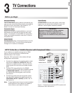
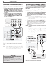
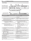
Composite Video Connection
Required: Analog stereo audio and composite video
cables supplied with the camcorder.
1. Connect a composite video cable from
VIDEO OUT
on the camcorder to
INPUT 3/VIDEO
or
VIDEO/Y
on
the TV.
2. Connect left (white) and right (red) audio cables
from
AUDIO OUT
on the camcorder to
INPUT 3, L
and
R
on the TV side panel.
Pr
Pb
574JEF1BOFM#PUUPN
Figure 13. Composite video connections for a camcorder
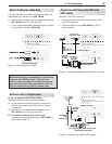
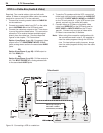
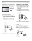
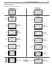
HDMI Connection
Required: HDMI cable supplied with the camcorder.
Connect the camcorder to the TV’s HDMI jack.
Note: Only the LT-40134 model has an HDMI input on
the side panel of the TV. For other models, use
an HDMI jack located on TV back panel #2.
4JEF1BOFM)%.*+BDL
BWBJMBCMFPONPEFM
-5POMZ
574JEF1BOFM#PUUPN
Figure 15. HDMI connection for a camcorder.
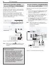
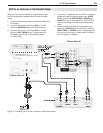
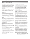
Component Y Pb Pr Video Connection
Required: Analog stereo audio and component video
cables supplied with the camcorder.
1. Connect component video cables from
VIDEO
OUT
on the camcorder to one of the TV’s sets of
COMPONENT INPUTS
jacks (TV Back Panel #1 or
TV Side Panel).
2. Connect left (white) and right (red) audio cables
from
AUDIO OUT
on the camcorder to
COMPONENT 3
,
L
and
R
jacks on the TV side panel.
574JEF1BOFM#PUUPN
Figure 14. Component video connections for a camcorder
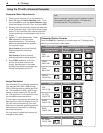
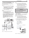
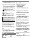
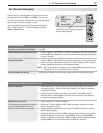
Camcorder
Inputs on the side of the TV offer the most convenient
way to connect a camcorder. If your TV model does
not have a side input matching the camcorder’s output,
use one of the matching jacks on the back of the TV.
Jacks on the TV side
panel offer the most
convenient way to
connect a camcorder