16
17
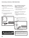
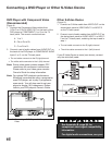
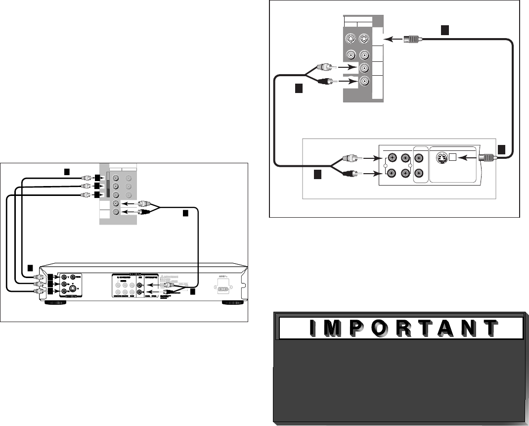
DVD Player with Component Video
(Recommended)
(Figure 9)
1. Connect the Component Video cables from
(YCb Cr or YPbPr) VIDEO OUT on the back of the
DVD player to COMPONENT (1 or 2) on the TV
back panel. The correct connections are:
A.
Y to Y
B. Cb or Pb to Pb
C. Cr or Pr to Pr
2.
Connect a set of audio cables from AUDIO OUT on
the back of the DVD player to COMPONENT AUDIO
Input (1 or 2) on the TV back panel.
• The red cable connects to the R (right)channel
• The white cable connects to the L (left) channel
Note: Some video game systems support DTV
resolutions via component connections.
Please refer to your video game console
Owner’s Guide for setup information.
Note: For optimal DVD playback performance,
Mitsubishi recommends using a progressive
scan DVD player, set to play in progressive
scan mode. You will also want to set your
player to display 16:9 widescreen. Please
refer to your DVD player’s Owner’s Guide.
Figure 9. Connecting a DVD Player with Component
Video.
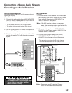
Figure 10. Connecting an S-Video Device.
Connecting a DVD Player or Other S-Video Device
See Appendix B, page 59, for
component video signal compatibility
information.
For digital audio connections, see your
Other S-Video Device
(Figure 10)
1.
Connect an S-Video cable from VIDEO OUT on the
device back panel to VIDEO INPUT-1 or INPUT-2
on the TV back panel.
2.
Connect a set of audio cables from AUDIO OUT on
the device back panel to AUDIO INPUT-1 or INPUT-
2 on the TV back panel, matching the input used in
step 1.
• The red cable connects to the R (right) channel
• The white cable connects to the L (left) channel
If your S-Video Device is mono (non-stereo), connect
only the white (left) cable.


