8 - 61 8 - 61
MELSEC-Q
8 TROUBLESHOOTING
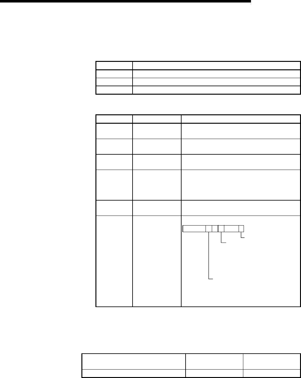
(2) H/W switch information
The following tables list the switch setting data for the master module.
2)-a: The switch settings for the hardware mounted to the master
module
Item Description
STx10 10 position of station number setting switch.
STx 1 1 position of station number setting switch.
MODE Mode setting switch.
2)-b: The switch data that has been actually set on the master module
Item Description Display range
NETNO. Setting value of
network No.
0 to 239
GRPNO. Setting value of
group number
0 to 9
STNO. Setting of station
number
1 to 64 (7DH: remote master station)
MODE Setting value of
operation mode
0: Online
7: Self loopback-test
8: Internal self- loopback test
9: Hardware test
BAUD 25 Mbps compatible 0: 10 Mbps
1: 25 Mbps
CONFIG Return mode,
parameter status
setting value
b15
b7
b0
b9
10
00
1: Fixed
Return mode
0: Remote master station returns as
master operating station
(control station).
1: Remote master station returns as
sub-master operating station
(standby station).
Parameter status
0: Without parameters for remote sub-
master station
1: With parameters for remote master
station/remote sub-master station
(2) H/W information for remote I/O module
Use the following SB/SW to confirm the H/W information of the remote I/O
module.
For details, refer to Appendix 2 and Appendix 3.
Setting status of the remote I/O module
SB0040 to 44
SB0058 to 69
SW0040 to 46
SW0054 to 68
Operating status of the remote I/O module SB0047 to 49 SW0047 to 4A


