MODELS: WD-57733 / WD-65733 / WD-73733 / WD-57734 / WD-65734 / WD-73734 / WD-C657
WD-Y577 / WD-Y657 / WD-57833 / WD-65833 / WD-73833
Page 32
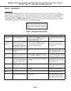
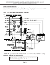
3. Adjustment Function Selection
Use the “AUDIO” button to select a specific Adjustment Function.
NOTE: There are 2 Service Functions on these chassis: “TVM” and the “ASIC” function.
4. Adjustment Selection
Use the “VIDEO” button to select a specific electrical adjustment, “1.HVPOS”.
5. Adjusting Data
After selecting an adjustment item, use the “UP/DOWN/LEFT/RIGHT” buttons to change
adjustment.
• If the “UP/DOWN” button is pressed, the VPOS adjustment data changes.
• If the “LEFT/RIGHT” button is pressed, the HPOS adjustment data changes.
6. Saving data
Press “ENTER” to save the adjustment data in memory.
The display characters go red for approximately one second in this step.
Note: If the circuit adjustment mode is terminated without pressing
“ENTER”, changes in adjustment data are not saved.
16-Point Geometric Distortion Correction
Summary:
• Calculates new geometry based on positional movement of 16 points
• 16-Point correction replaces mechanical adjustment
• Alignment does not effect center, it only affects the edge geometry
• When the adjustment mode is activated all 16 points will be set to default position
• Pressing the INFO button will perform the distortion calculation and finalize the adjustment
• The adjustment is not saved until the ENTER button has been pressed
• Pressing the ENTER button will save, however it will not indicate this in any manner
• For the adjustment to work properly all 16 points must be aligned before pressing INFO button
NOTE: In the PC Input or FX Game Mode electronic geometric correction is not available.
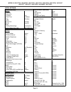
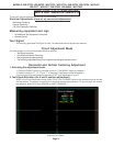
1. Activating the Adjustment Mode
1. Press the “MENU” button on a remote hand unit. (The “MENU” display will appear.)
2. Press the buttons “2”, “4”, “5”, “7”, pause and then press “0” (Data Selection Mode will appear)
3. Use the UP/DOWN arrows to highlight “MANUAL KEYSTONE GEOMETRY ALIGNMENT” and press ENTER.
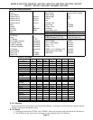
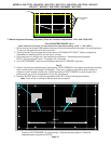
The following pattern appears (see next page).
NOTE 1: If data is out of range, you may need to perform reset - Press (1) then INFO). This nulls all correction data.
NOTE 2: To restore the original factory correction data, repeat steps 1 thru 3, select “RESTORE KEYSTONE
GEOMETRY FROM BACK UP” and press “ENTER”.
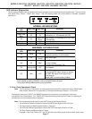
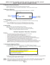
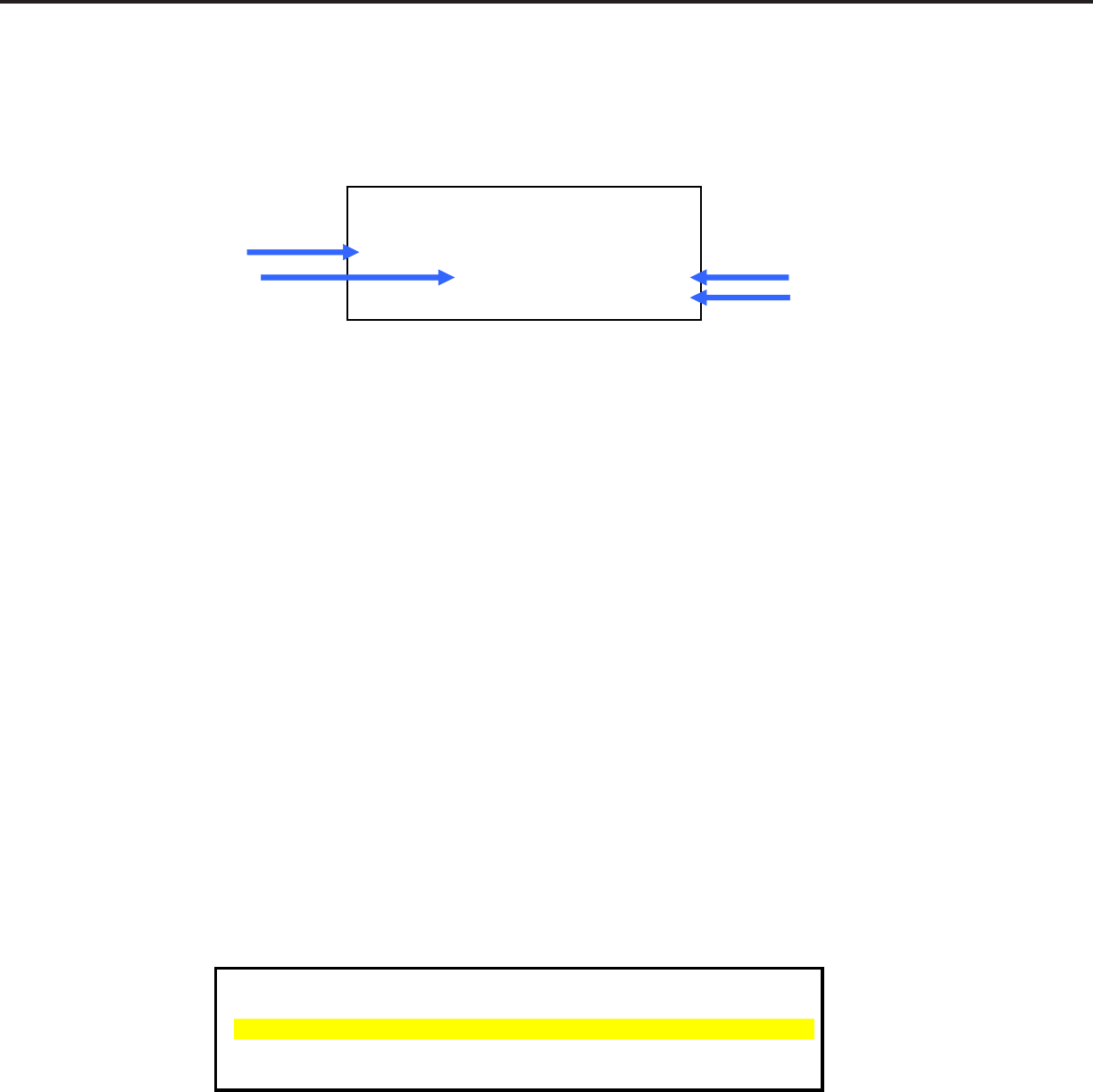
MENU + 2 4 5 7
ISF
Function
TVM
Adjustment
1. HVPOS 65533
Data (HPOS)
65530 Data (VPOS)
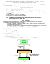
RESTORE ALIGNMENT AND WHITE BALANCE SETTINGS FROM BACKUP
RESTORE KEYSTONE GEOMETRY FROM BACKUP
MANUAL KEYSTONE GEOMETRY ALIGNMENT
LOAD INDEX DELAY FROM ENGINE
COPY SETTINGS TO BACKUP
WARNING - only use "COPY SETTINGS TO BACKUP" after replacing PWB-TERMINAL
Data Selection Mode
MENU + 2 4 5 7 + 0


