


FX1S Series Programmable Controllers Installation Notes 3
3-2
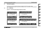
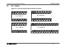
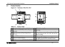
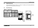
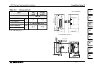
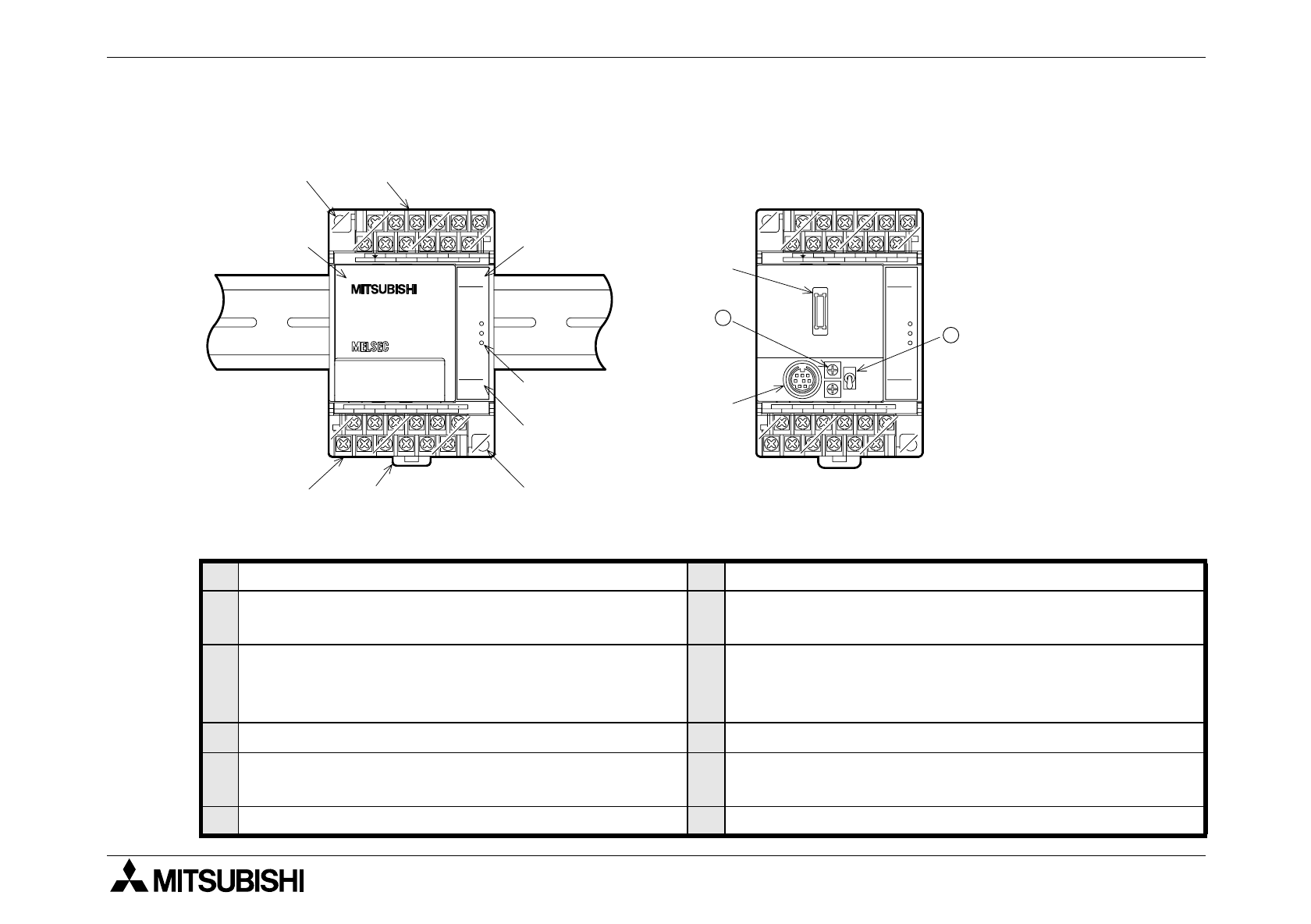
3.1 Product Outline
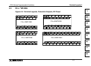
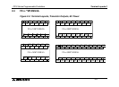
Figure 3.1: Features of the FX
1S
PLC
Table 3.1: Feature Table
1
Direct Mounting Holes (4.5 mm<0.17"> Diameter)
7
DIN Rail Mounting Clip
2
Input Terminals (24V DC) and Power Supply
Te r m i n a l s
8
To p C o ver
3
Output Terminals and Power Supply Source
Te r m i n a l s
9
Optional Equipment port - Memory Cassette, FX
1N
-
232, 422, 485, 8AV, 4EX, 2EYT, 2AD, 1DA and CNV
BDs, FX
1N
-5DM
4
Input LED Status Indicators
10
Programming Port
5
Output LED Status Indicators
11
Analog Trim Pots. D8030 read from VR1, the top trim
pot. D8031 read from VR2, the bottom trim pot.
6
PLC Status Indicators (POWER, RUN, ERROR)
12
Run/Stop Switch
X4
X5
Y3
X6
LN
X0
X2
S/S
X7X1
X3
0V
Y5
Y0 Y2Y1
COM2COM1
24V
COM0
POWER
ERROR
FX
1S
-14MR
IN
OUT
45
23
RUN
01
6754
14MR
01
23
Y4
100 - 240
VAC
➈
➀
➁
➇
➂
➆
➄
➃
➅
➉
POWER
ERROR
IN
OUT
45
23
RUN
01
6754
01
23
➀
- ES/UL
11
12
X4
X5
X6
LN
X0
X2
S/S
X7X1
X3
100 - 240
VAC
FX
1S
-14MR
Y3
0V
Y5
Y0 Y2Y1
COM2COM1
24V
COM0
14MR
Y4
- ES/UL