


E – 6
DVI
L/MONO
L/MONO
RGB 2
RGB 1
VIDEO 1
VIDEO 2
S
-
VIDEO
AUDIO OUT
R/Cr
G/Y
B/Cb
V
H/HV
MONITOR OUT
R
L/MONO
R
L/MONO
R
L/MONO
R
R
1
5
8
9
11
10
12
13
7
6
3
4
2
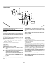
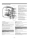
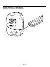
1. DVI Connector
This connector can be used to accept digital or analog signal output
from a computer with a DVI connector.
2. DVI Audio Input Jacks (RCA)
These are the left channel and the right audio inputs for stereo sound
coming from the equipment connected to a computer with DVI output.
L/MONO
This is your left channel audio input for stereo sound from the equip-
ment connected to a computer with DVI output.
The L/MONO jack also serves as your monaural audio input.
R
This is your right channel audio input for stereo sound from the equip-
ment connected to a computer with DVI output.
3. RGB 2 Connector (Mini D-Sub 15 pin)
Connect your PC, Macintosh, DVD player with Y/Cb/Cr outputs or other
RGB equipment. The optional Component V. Cable is required for Y/
Cb/ Cr input connection.
NOTE:
The RGB2 connector does not support the Switcher Control mode.
4. RGB 2 Audio Input Jacks (RCA)
L/MONO
This is your left channel audio input for stereo sound coming from the
RGB Input 2 source.
This also serves as your monaural audio input.
R
This is your right channel audio input for stereo sound from the RGB
Input 2 source.
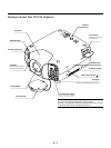
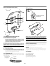
Front Terminal Panel (Right)
5. MONITOR OUT Connector (Mini D-Sub 15
pin)
You can use this connector to loop your computer
image an external monitor from either the RGB 1,
RGB 2 or DVI analog input source.
6. RGB 1 Input Connectors (BNC)
Connect R,G,B,H (Horizontal sync) and V (Vertical
sync) outputs of external equipment such as the NEC
ISS-6020Switcher.
If using a component with a combined sync (SYNC)
output, connect it to the H/V terminal. When using
luminance and color-difference signals of HDTV and
DVD, connect Pr/Cr to the R,Y to the G and Pb/Cb
to the B input of the projector.
7. RGB 1 Audio Input Jacks (RCA)
L/MONO
This is your left channel audio input for stereo sound
coming from the RGB Input 1 source.
This also serves as your monaural audio input.
R
This is your right channel audio input for stereo sound
from the RGB Input 1 source.
8. VIDEO 1 Input Connector (BNC)
Connect a VCR, DVD player, laser disc player, or
document camera here to project video.
9. VIDEO 2 Input Connector (RCA)
Connect a VCR, DVD player, laser disc player, or
document camera here to project video.
10. VIDEO Audio Input Jacks (RCA)
L/MONO
This is your left channel audio input for stereo sound coming from the
VIDEO 1 or VIDEO 2 source.
This also serves as your monaural audio input.
R
This is your right channel audio input for stereo sound from the VIDEO
1 or VIDEO 2 source.
11. S-VIDEO Input Connector (Mini DIN 4 pin)
Here is where you connect the S-Video input from an external source
such as a VCR or laser disc player.
NOTE: S-Video provides more vivid color and higher resolution than the tradi-
tional composite video format.
12. S-VIDEO Audio Input Jacks (RCA)
L/MONO
This is your left channel audio input for stereo sound coming from the
S-VIDEO source.
This also serves as your monaural audio input.
R
This is your right channel audio input for stereo sound from the S-
VIDEO source.
13. AUDIO OUT Jacks (RCA)
You can use this connector to output sound from the currently selected
input source (RGB 1, RGB 2, VIDEO 1, VIDEO 2, S-VIDEO or DVI
[digital/analog] ). Output sound level can be adjusted in accordance
with the sound level of the internal speaker.