


46
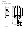
6. Appendix
6-7. Pin Assignment and Functions of Terminal
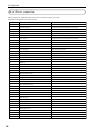
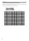
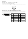
6-7-1. PC CONTROL connector (D-Sub 9 pin)
This is an RS-232C interface for controlling the projector head from a PC. The projector operates as a DCE (Data Communication
Equipment), so use a straight cable when connecting to a PC.
Pin
No.
1
2
3
4
5
6
7
8
9
RS-232C
Signal Name
CD
RXD
TXD
DTR
GND
DSR
RTS
CTS
RI
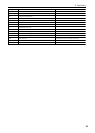
Functions as RS-232C
Carrier detection
Reception data
Transmission data
Data Terminal ready (Note 1)
Signal GND
Data set ready (Note 1)
Transmission request
Transmission available
Ring indicator
Projector Connector Operation
Not used (N.C.)
Data transmission to an external device
Data reception from an external device
Connection to 6 pins
Signal GND
Connection to 4 pins
SYSTEM (Note 2): Hi-Z (Not used)
CINEMA (Note 2): Hi-Z (Used)
SYSTEM (Note 2): Fixed at -6.5 V (Not used)
CINEMA (Note 2): ± 10.5 V (Used: Depends
on communication status)
Not used (N.C.)
Note 1: Do not use DTR and DSR signals when communicating.
Note 2: Connector operations vary according to the PC control signal switch
(CINEMA/SYSTEM). (When in SYSTEM, do not use RTS and CTS signals.)
12345
6789
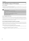
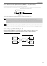
Internal Configuration Diagram of RS-232C Communication System
PC Control Signal Switch
RS-232C
Connector
PC
Cinema
Control Block
System
Control Block
Projector NC800C
CINEMA
SYSTEM