


2.3 Reverse Acting Calibration
2.3.1 When calibrated to operate in the reverse acting mode the minimum input signal produces the maximum output
pressure and increasing the input signal results in decreasing the output pressure. Setting the unit to operate in
the reverse acting mode is accomplished by positioning internal electrical switches.
Do not reverse the input leads.
2.3.2 Disconnect input signal and supply pressure. Take off the top cover by removing the four screws.
Avoid touching circuit board. Shorting possible.
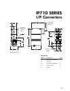
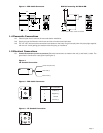
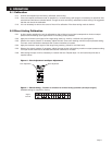
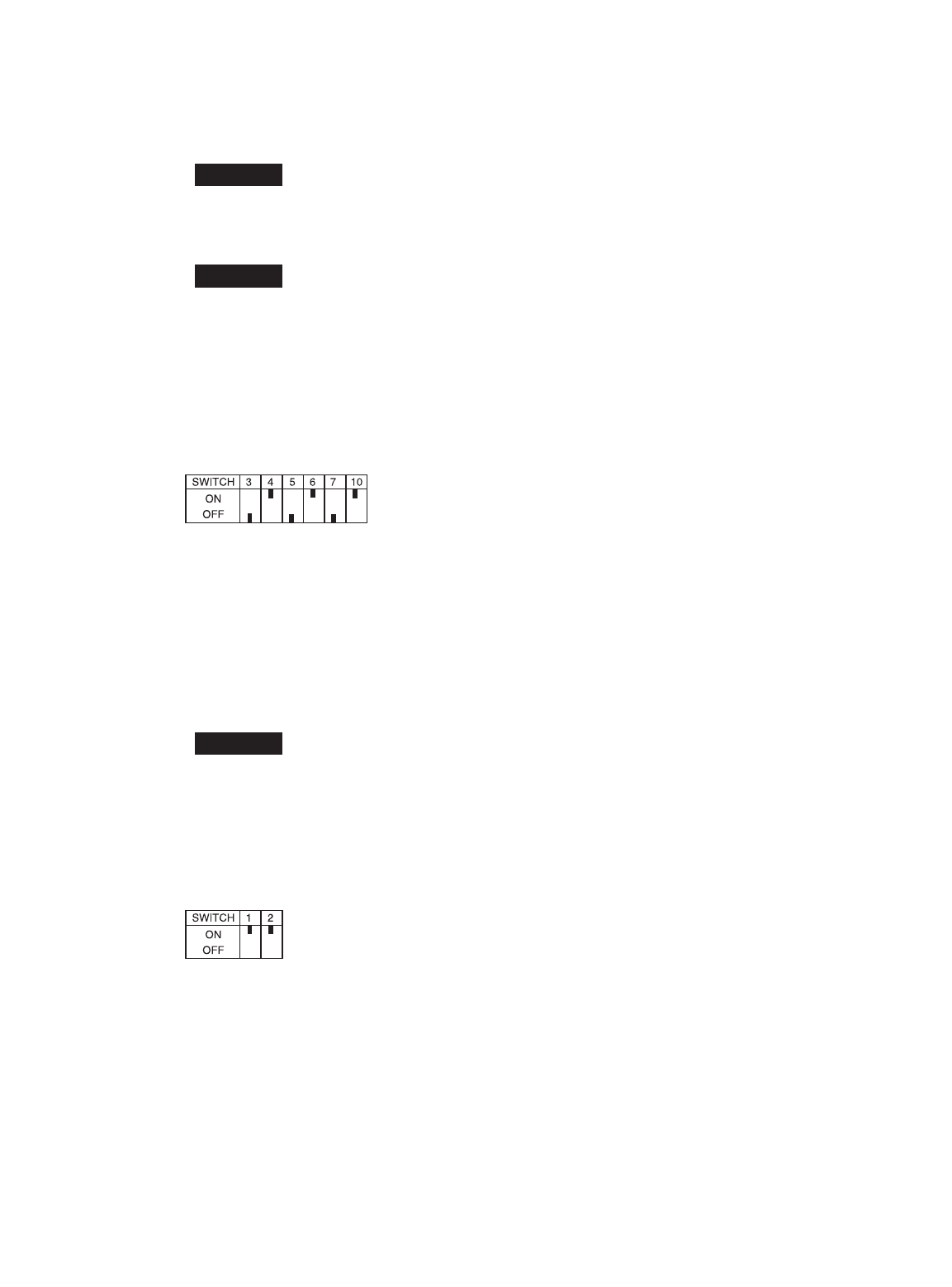
2.3.3 Position switches as illustrated in figure 8. Replace cover.
2.3.4 Set the input signal to the minimum valve being used. Turn the zero screw to set the maximum output pressure.
2.3.5 Set the span by applying the maximum input signal. Turn the span screw to set the minimum output pressure.
2.3.6 It may be necessary to repeat steps 2.3.4 – 2.3.5 until both end points are at desired values.
Figure 8 - Position of switches for Reverse Acting Operation
Note: Switches not shown match Direct Acting Settings (see figure 7).
2.4 Split Range
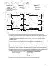
2.4.1 When calibrated to operate in the split range mode, a full input signal (i.e. 4-20mA) will operate the unit
at one half the normal output span (i.e. 3-9 psig, 9-15 psig). Setting the unit to operate in the split range
mode is accomplished by positioning internal electrical switches.
2.4.2 Disconnect input signal and supply pressure. Take off the top cover of the unit by removing the four screws.
Avoid touching circuit board. Shorting possible.
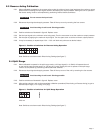
2.4.3 Position switches as illustrated in figure 9. Replace cover
2.4.4 After setting switches, refer to the appropriate calibration procedure (Direct Acting or Reverse Acting) to get to
desired output range (i.e. 3-9 psig, 9-15 psig).
Figure 9 - Position of switches for Split Range Operation
4-20 mA
Note: Switches not shown match Direct Acting Settings (see figure 7).
CAUTION
CAUTION
CAUTION
Page 7