


2. OPERATION
2.1 Calibration
2.1.1 All units are shipped from the factory calibrated, direct acting.
2
.1.2 If the user requires a different mode of operation (i.e. reverse acting, split range) it is necessary to reposition inter-
n
al electrical switches as indicated below. Though the units are factory calibrated for direct acting it is suggested
t
hat the user check the calibration.
2.1.3 It is not necessary to remove the cover of the unit for calibration if the direct acting mode is desired.
2.2 Direct Acting Calibration
2
.2.1 In direct acting operation the unit is calibrated so that minimum input signal corresponds to minimum output
pressure and increasing input signal results in increasing output pressure.
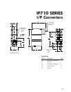
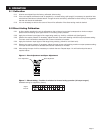
2.2.2 Apply the minimum input signal of the range being used (e.g. 4mA for a 4-20mA unit) (see figure 6).
2.2.3 Observe the output pressure. If necessary, adjust the zero screw until reaching minimum output pressure setting.
Turn zero screw clockwise to decrease and counter clockwise to increase.
2.2.4 Apply the maximum input signal of the range being used (e.g. 20mA for a 4-20mA unit).
2.2.5 Observe the output pressure. If necessary, adjust the span screw until reaching maximum output pressure setting.
Turn span screw clockwise to decrease and counter clockwise to increase.
2.2.6 After setting the span it will be necessary to recheck the zero. Repeat steps 1-4 until both end points are at
required values.
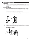
Figure 6 - Zero Adjustment and Span Adjustment
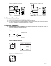
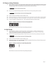
Figure 7 - Direct Acting -
Position of switches for forward acting operation (all output ranges).
Standard setting as supplied by factory.
Page 6
Zero Adjustment Span Adjustment
Signal
4-20 mA