CONNECTORS, SWITCHES & INDICATORS
CONNECTORS
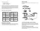
The OmniHawk™ has three interface connectors: a fiber optic transmitter
and receiver pair, an RJ45 jack, and a DB9 male connector.
The DB9 connector and the chassis are designed to attach directly to the
rear of a workstation network interface card. The jack screws ensure a solid
connection.
The RJ45 connector is designed to attach directly to a hub lobe or ring out
via a CAT-5 patch cable. The RJ45 connector may attach to a ring in with a
crossed patch cable (transmit and receive pairs crossed).
Note that only one copper interface may be used at a time. Other connec-
tions are possible with special cables. Omnitron’s technical support depart-
ment can assist you with your special needs.
SWITCHES
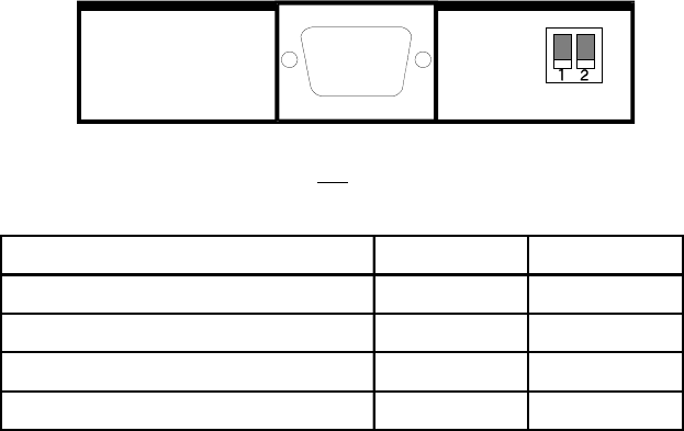
The OmniHawk™ has two switches which control the attachment mode.
The switches are located to the right of the DB9 connector.
Both switches are placed in the UP position at the factory. The following
table explains the switch settings.
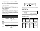
ATTACHMENT MODE SWITCH 1 SWITCH 2
Automatic Sensing Up Up
UTP/STP --> RO or Station Up Down
UTP/STP --> RI or Lobe Down Up
Self Test / Media Test Down Down
CONNECTORS
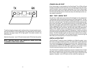
In addition to the two switches there are four LED indicators in a 2 x 2
cluster. Refer to the drawing below.
2
TECHNICAL SPECIFICATIONS
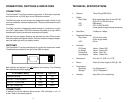
• Protocol: Token Ring (IEEE 802.5)
• Cables
Fiber Optic: Multi-mode glass fiber of sizes 50/125,
62.5/125, or 100/140 micron
STP: DB9 female
UTP: CAT-5 (EIA/TIA 568):
(lower grade wiring at shorter distances)
• Data Rate: 16 Mbps or 4 Mbps
• Supported Distances
Fiber Optic: 2.5 Km multi-mode
20 Km single-mode
UTP: 300 m
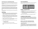
• Indicators
FO Ready Yellow - Green LED
Cu Ready Yellow - Green LED
Power/Error Yellow - Red LED
Insert Status Yellow - Green LED
• Dimensions: W: 3.46” x D: 2.83” x H: 0.78”
• Power: External Power Supply 9 VDC @ 1.2A
• Temperature
Operating: 0 to 45 degrees C
Storage: -40 to 75 degrees C
• Humidity: Up to 90% (non condensing)
11


