


The operational modes are:
1. AUTOMATIC SENSING
2. UTP/STP —> RO or STATION
3. UTP/STP —> RI or LOBE
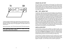
The power / error LED turns red when an attachment error occurs. An error
can only occur when attaching to active devices (devices which signal for
insertion with phantom current or the fiber optic key). The error condition
occurs when copper device initiates the phantom current and the fiber optic
device initiates the fiber optic key. In Token Ring, the active insertion pro-
cess may only be directed from one direction.
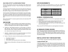
SELF TEST / MEDIA TEST MODE
FIBER READY
(top left)
MEANING
COPPER
READY (top
right)
MEANING
GREEN
Data received from
fiber
GREEN
Data received from
copper
OFF
No data is being
received from fiber
OFF
No data is being
received from coppe
r
POWER /
ERROR (bot.
left)
MEANING
INSERT
STATUS (bot.
right)
MEANING
YELLOW Power is on YELLOW
The OmniHawk™ is
in the self test /
media test mode.
DIAGNOSTIC FEATURES
The OmniHawk™ diagnostic features make it easy to install and maintain.
There are four levels of diagnostics: Power-On LED Test, Self Test / Media
Test, Installation Test, and run-time ready and error monitoring.
4
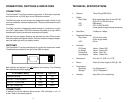
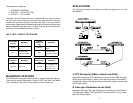
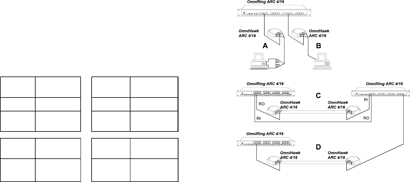
APPLICATIONS
The following drawing illustrates three different applications of the
OmniHawk™.
A. STP Workstation (DB9) to distant hub (RJ45)
Application A shows an STP workstation connecting via its DB9 connector
directly to one OmniHawk™, which is connected to a second OmniHawk™
via fiber optic cables. The last connection to the hub is made via a standard
CAT-5 patch cable.
B. Fiber optic Workstation to hub (RJ45)
Application B shows a fiber optic workstation connecting to an OmniHawk™
vi its fiber optic cables. The OmniHawk™ connects to the hub via a stan-
dard CAT-5 patch cable.
9