


III. PRELIMINARY ALIGNMENT SETUP
The following procedures are intended for complete
“Geometry/Convergence” setup. Use the customer’s signal for
doing phase, and size adjustments. You can use the internal pat-
terns for shape and convergence if the customer signal sources do
not have a cross-hatch pattern.
If you are realigning a single CRT, due to replacement, or doing
alignment touch up, perform the following steps as needed.
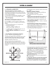
1. Yoke Tilt Alignment
Use a cross-hair or cross-hatch pattern. Monitor only the center-
most horizontal line of the pattern to check yoke tilt.
Do not use SW9501, on the 9-1510 module, to disable conver-
gence. The vertical circuit is not disabled, only the horizontal is
disabled.
a. Set Horizontal DC centering to “0” (red, green, blue).
b. Set Vertical DC centering:
Floor: Red = -30; Green = -20; Blue = -30.
Ceiling : Red = 30; Green = 20; Blue = 30.
c. In geometry mode and convergence mode (green, red, and
blue) set “SKEW” H = 0 and “SKEW” V = 0.
d. Adjust the Red, Green, and Blue yokes for no horizontal tilt
or twist.
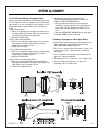
2. Yoke Ring Magnet and Astigmatator Alignment
Verify Only - This is not a normal field adjustment.
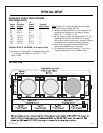
The astigmatator assembly should be mounted 62.5 mm from the
video output module (from the front edge of the video output
module to the six pole rings). Refer to the figure on page 24.
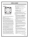
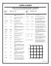
Astigmatator Alignment Verification Test
Adjust for the best electrical and mechanical focus.
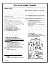
Verify spot alignment by rotating Green electrical focus slightly
CW to CCW. The Dot shape should not tail or flair. The bright area
should remain in the center of the haloed area. Refer to the fig-
ure below.
If this test shows a need for astimatator alignment perform steps
“a” - “l” below.
Astigmatator Alignment Procedure
a. Set the display/sync mode to Forced Mode 6 (HDTV33) and
select a cross-hatch or dot pattern.
b. Cut off Red and Blue video or cover the CRT lens
assemblies.
c. Set Green electrical focus slightly CCW. This is to make a near
display center dot dimly haloed with a bright center. The
haloed effect will also be visible with the cross-hatch lines.
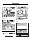
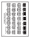
d. Use the astigmatator 4-pole magnet to shape the halo and
bright spot as round as possible.
e. Use the astigmatator 6-pole magnet, if needed, to help shape
the halo and spot round.
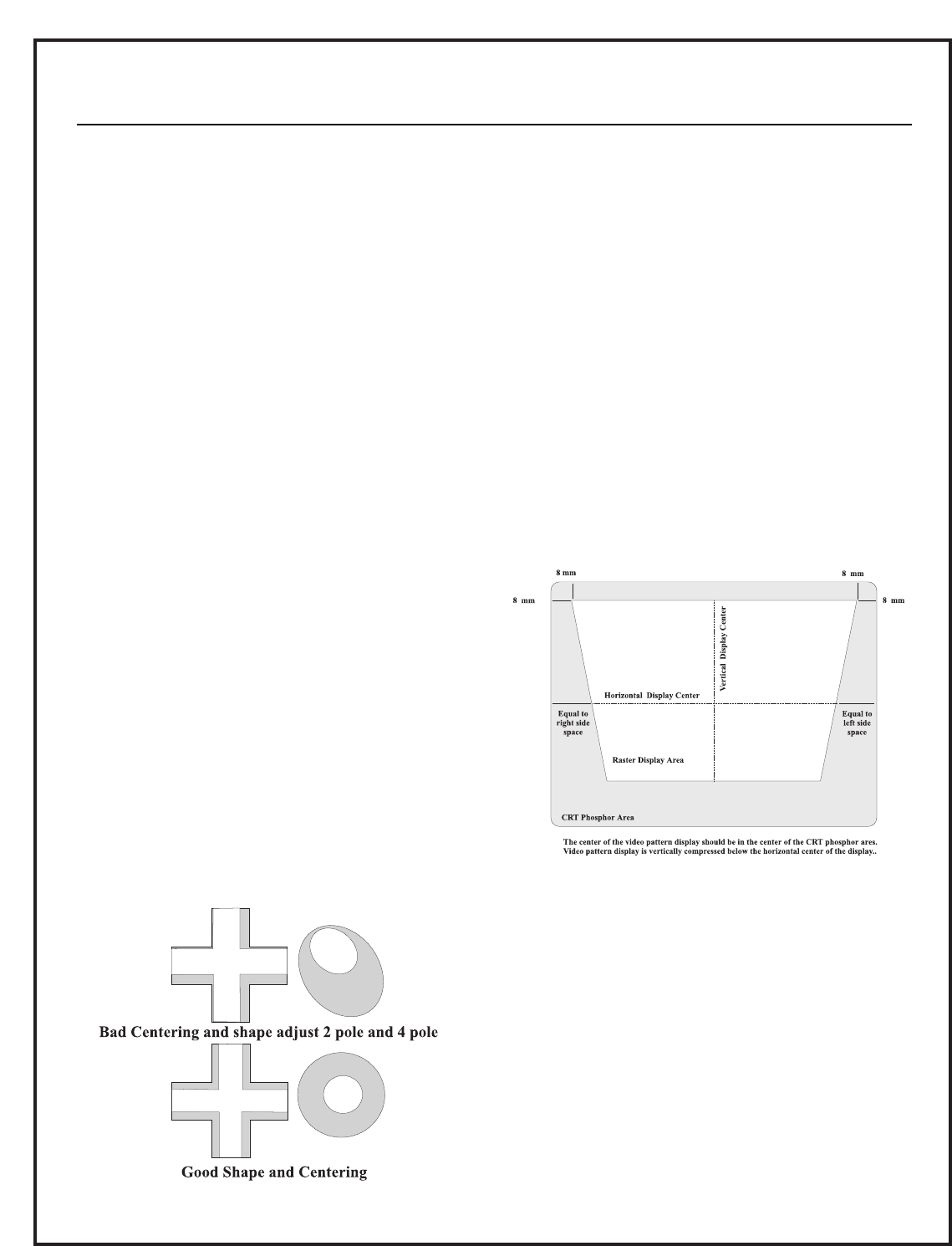
f. Use the astigmatator 2-pole magnet (refer to the figure at
bottom left of this page) to center the bright spot within the
halo. You may also use an intersection, of the cross-hatch, to
center the bright area within the haloed area.
g. Use the main yoke magnets to position the signal raster center
to the CRT face center. Refer to figure below.
h. Verify spot alignment by rotating Green electrical focus slightly
CW to CCW. The Dot shape should not tail or flair. The bright
area should remain in the center of the haloed area.
i. Repeat steps “c” thru “h” as needed to obtain the smallest and
best round Green center dot with no shape flaring.
j. Adjust for the best electrical and mechanical focus.
k. Repeat steps “c” - “j” for the Red and Blue displays.
l. Exit forced mode 6 and return to normal video. Set
Brightness and Contrast to 50.
Note: The yoke adjustments should not be touched during the
remaining setup steps.
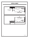
3. Ceiling/Front Projection Lens Angle Focus Alignment
If this PRO900X system is equipped with the “lens assembly
focus” spring, the following procedure must be completed. This
procedure must be completed as part of the system mechanical
3276-A
PAGE 22
SYSTEM ALIGNMENT