PAGE 27
3276-A
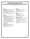
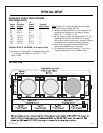
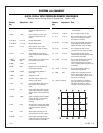
1. SMALL H. & V. Statics Set center of video for best overlap
ARROWS with Green (this may have to be
‘tweaked’ during this alignment
procedure.)
2. SIZE H. Size Set to match Green at C and D.
3. SIZE V. Size Set to match Green at A and B.
4. LIN T-B L-R H. Lin L-R Match Green at C and D; Iterate with
H. Size if necessary.
5. LIN T,B L-R V. Lin T-B Match Green at A and B iterate with
V. Size if necessary.
6. LIN C and Lin C and Match Green at 4, center line vertical
H. SIZE SIZE axis, midway between Z and D.
7. LI-LIN H. LI LIN Match Green at 3, center line vertical
axis, midway between C & Z and LI-LIN
(Press key twice to get the second
function.) Caution: H. LIN C also
affects this; adjust in correct order
above.)
8. LIN C V. Lin C Match Green at 7 and 8.
9. SKEW V. Skew Match Green at C and D.
10. BOW V. Bow Match Green at C and D.
11. SKEW H. Skew Match Green at A and B.
12. BOW H. Bow Match Green at A and B.
13. KEY V. Key Balance error with Green at bottom
edge G-H (left and right edges move
in opposite directions; center is
stable).
14. PIN V. Pin Match Green at right edge corners G
& H (corners G & H move in same
direction; center B is stable).
15. S-ING V. ‘S’ Balance error at bottom edge in areas
K & M (middle areas K & M move
in opposite directions; center B and
ends G & H are stationary).
16. W-M V. W-M Balance error at bottom edge in
areas K & M (middle areas K & M move
in same direction, center B and ends
G & H are stationary).
17. KEY H. key Balance error with Green at right
edge corners F & H (top and bottom
move in opposite directions; center D
is stable).
18. PIN H. Pin Match Green at F & H (corners F & H
move in same direction; center D is
stable).
19. S-ING H. ‘S’ Balance error at right edge in areas &
Q (middle areas O & Q move in opposite
direction; center D and ends F & H are
stationary).
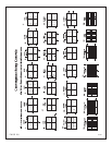
20. T/L KEY V. Top Key Balance error with Green at top corners
E & F straight with respect to screen
border (left and right move in opposite
directions; center A is stable).
21. T/L KEY V. Top Pin Match Green at top edge comers E & F
(comers E & F move in same direction;
center A is stable).
22. T/L S-ING V. ‘S’ Balance error at bottom edge in areas J
& L (middle areas J & L move in oppo-
site directions; center A and ends E & F
are stationary).
23. T/L KEY H. Left Key Balance error with Green at left corners
E & G (top and bottom move in oppo-
site directions; center C is stable).
24. T/L PIN H. Left Pin Match Green at left edge corners E & G
(corners E & G move in same direction,
center C is stable).
25. T/L S-ING H. ‘S’ Balance error at left edge in areas N & P
(middle areas N & P move in opposite
directions; center C and ends E & G are
stationary).
26. IN KEY H. In Key Average error with Green in middle areas
J, K, and L, M (ends move in opposite
direction centers 3 & 4 are stable, may
require iteration with H. Skew, H. Key).
27. IN PIN H. In Pin Match Green in middle areas J, K, and L,
M (ends move in same direction: center
is stable; may require iteration with H.
Bow, H. Pin).
28. IN KEY V. In Key Average error with Green in middle areas
N, O, and P, Q (ends move in opposite
direction centers 7 & 8 are stable, may
require iteration with V. Skew, V. Key).
29. IN-PIN V. In Pin Match Green in middle areas N, O and P,
Q (may require iteration with V. Bow, V.
Pin)
30. Touch up all controls Due to the interaction of IN-Controls,
Key Controls and Pin controls for best
overall convergence, it may be necessary
to tweak the other controls. This should
only require minor adjustments of each
control.
It may be necessary to perform this
procedure twice to get optimal
performance.
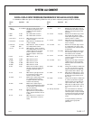
DIGITAL DISPLAY SETUP PROCEDURE CONVERGENCE OF RED AND BLUE ONTO GREEN
It is desirable to Mute color you are not adjusting. Select the color you want to adjust by pressing the RED or BLUE key.
Remote Adjustment Goal Remote Adjustment Goal
Key Key
SYSTEM ALIGNMENT


