


48
Setup menus
The underlined items indicates the initial setting.
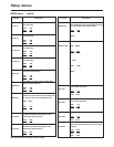
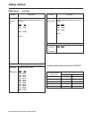
USER menu
<AUDIO>
No./Item Description No./Item Description
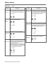
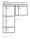
701
CH1 IN LV
This selects the audio input (CH1) reference
level switching.
0000 4dB
0001 0dB
0002 –20dB
702
CH2 IN LV
This selects the audio input (CH2) reference
level switching.
0000 4dB
0001 0dB
0002 –20dB
706
CH1 OUT LV
This selects the audio output (CH1) reference
level switching.
0000 4dB
0001
0dB
0002 –20dB
707
CH2 OUT LV
This selects the audio output (CH2) reference
level switching.
0000 4dB
0001 0dB
0002 –20dB
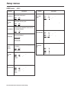
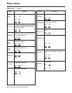
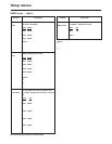
711
MONIL OUT
LV
This selects the audio monitor output (Lch)
reference level switching.
0000 4dB
0001 0dB
0002 –20dB
712
MONIR OUT
LV
This selects the audio monitor output (Rch)
reference level switching.
0000 4dB
0001 0dB
0002 –20dB
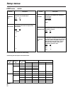
715
CH1 IN SEL
This selects the CH1 input when USER SET
has been selected by pressing the unit’s
AUDIO input selector button.
0000 ANA
: Analog input.
0001 DIGI
: Digital input.
716
CH2 IN SEL
This selects the CH2 input when USER SET
has been selected by pressing the unit’s
AUDIO input selector button.
0000 ANA
: Analog input.
0001 DIGI
: Digital input.
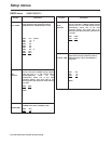
719
DIGI IN SEL
This selects the CH1 and CH2 digital input
when USER SET has been selected by pressing
the unit’s AUDIO input selector button.
0000 AES
: AES/EBU input
0001 SIF
: SDI input
<Note>
When no optional board (AJ-YA755G) has been
installed, setup menu No. 719 is not displayed.
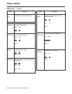
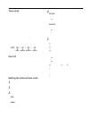
713
MONI OUT
This selects whether or not to couple the
volume level of the audio monitor output with
the volume control of the headphone jack.
0000 UNITY
:
Volume is output at a fixed level, regardless of
the position of the volume control.
0001 VAR
:
Audio monitor output volume is coupled to the
volume control.
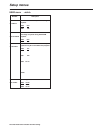
721
MONI CH SEL
This selects the monitor output.
0000 MANU
:
The output signal is as selected in MONITOR
SELECT buttons.
0001 AUTO
:
PCM AUDIO output is selected within the
–0.43 (–0.5)a to +1a speed range; CUE is
automatically selected for all other tape
speeds.
<Note>
The value for the DV/DVCAM tape is shown in
parenthesis ( ).
0002 PCM
:
The PCM AUDIO signal is output over the
–10a to +10a range.
<Note>
This setup menu’s setting takes effect when CH1
or CH2 has been selected by the L and R
MONITOR SELECT buttons on the front panel. (If
CUE has been selected, the cue signal will be
output at all the speeds regardless of the setup
menu’s setting.)
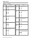
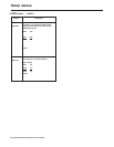
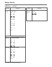
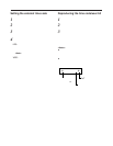
722
REC CH1
This selects the input signal to be recorded
on the audio CH1 track.
0000 CH1
: Audio input CH1 signal.
0001 CH2
: Audio input CH2 signal.
0002 CH1+2
: Mixed audio input CH1 and CH2
signal.
723
REC CH2
This selects the input signal to be recorded
on the audio CH2 track.
0000 CH1
: Audio input CH1 signal.
0001 CH2
: Audio input CH2 signal.
0002 CH1+2
: Mixed audio input CH1 and CH2
signal.
726
REC CUE
This selects the input signal recorded in CUE.
0001 CH1
: Audio CH1 input
0002 CH2
: Audio CH2 input
0003 CH1+2
: Audio CH1 and CH2 MIX signal
727
PB FADE
This selects the processing method for the
audio edit points (IN point, OUT point) during
playback.
0000 AUTO
: According to the status during
recording.
0001 CUT
: Forced CUT
0002 FADE
: Forced FADE