


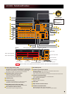

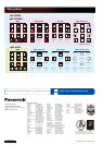
Rear
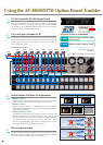
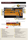
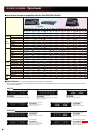
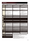
AW-HS50 Controls and Functions
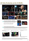
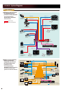
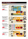
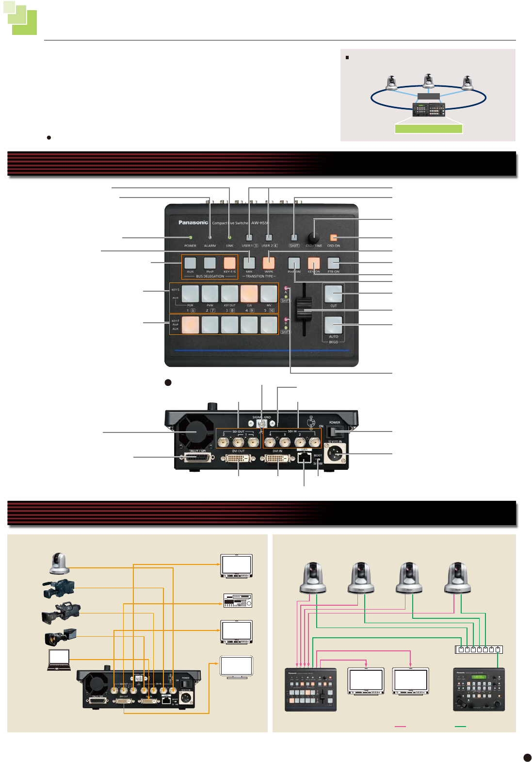
AW-HS50 System Diagrams
Compatible to small-scale shooting needs such as in-studio shootings.
*
3 The 2 signals from SDI OUT 1 are the same signals.
Saves space and enables comfortable operation of
simple systems required for business use.
AW-HS50
POWER indicator
ALARM indicator SHIFT button
OSD/TIME dial
LINK indicator USER buttons
HD-SDI
HD-SDI
HD-SDI
HD-SDI Monitor
HD-SDI
HD-SDI
HD-SDI
DVI-D
HD-SDI
HD-SDI Monitor
HD-SDI Monitor HD-SDI Monitor
DVI-D
BUS DELEGATION buttons
A bus crosspoint buttons
B bus crosspoint buttons
Cooling fan
Wire fastening fitting
SDI OUT connectors
DVI OUT connector
TALLY/GPI connector
DC IN connector
POWER switch
MIX button
KEY ON button
PinP ON button
Bus tally indicators
OSD ON button
WIPE button
FTB ON button
CUT button
AUTO button
Slide lever
SDI IN connectors
Ground terminal
DVI IN connector SERVICE switch
LAN connector
VTR
PC Monitor
PC
AW-HS50
AW-HE50S
AW-RP50
Monitor 1
Monitor 2
Switching hub
LAN cable
SDI video signal
Straight cable
*
3
*
3
HD Camera
HD Camera
HD Camera
HD Camera
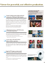
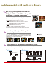
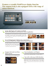
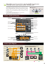
Highly efficient, stress-free operation by connecting the HD integrated camera
(AW-HE50S) with the remote camera controller (AW-RP50) via IP
*
1
.
The AW-HE50S camera setting information (iris, gain, etc.) obtained by the remote
camera controller AW-RP50 can be displayed on the AUX output or on the split
screens of the MultiViewer display. The switcher and remote camera controller
combination realizes smooth operation by enabling switcher's ON AIR tally
information to be sent to the AW-RP50 and bus images to be changed*
2
according
to the camera selection.
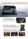
HUB
Camera 1
Controller Switcher
Up to 100 cameras
can be connected.
Camera 2
Camera 3
*
1 Only 1 AW-RP50 may be connected to the switcher via an IP connection.
*
2 Control bus targets: AUX, PVW, PinP, KEY-F
Full rack size
Controlled Via IP
Connection is not available with using the public network.
17