


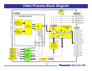
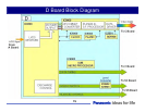


D Board Block Diagram
Discharge Control
IC9500 of the D board contains the Discharge Control circuit that analyzes the RGB and sync information of the
video signal to create the Scan data to drive the Scan operation (SC) board and Sustain data to drive the Sustain
operation (SS) board.
The SC board is responsible for the generation of the scan pulses. Scan pulses are used for initialization and
selection of the pixels..
The SS board is responsible for the generation of the sustain pulses. Sustain pulses are used to initialize and
control the brightness of the panel.
Data Drive
The LVDS receiver inside IC9500 of the D board converts the video signal to 10 bit RGB data, the original format.
The output is provided to IC9900.
IC9900 contains a format converter that changes the resolution of the signal to match the size of the panel. It
also contains the Plasma AI (Adaptive brightness Intensifier) circuits that analyzes the APL* for the distribution of
dark and bright components. IC9900 subsequently converts the picture data into the 10, 11, or 12 subfields data
to feed the two C boards.
The C boards are buffer boards that are used to distribute data to the shift registers of the panel.
The level converter ICs are level shifters that changes the voltage level of the data from 3.3V to 5V.
IC9200 is a clock generator.
IC9303 is a non-volatile memory chip that contains parameters for driving the panel.
IC9901 is a memory chip that is used for sub-field conversion.
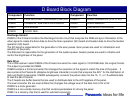
Component Function Component Function
IC9500 LVDS RECEIVER / DISCHARGE CONTROL IC9802-3 LEVEL CONVERTER (3.3V => 5V)
IC9900 PLASMA AI / SUB-FIELD PROCESSOR IC9303 FLASH MEMORY
IC9901 DDR SDRAM IC9003 SUB MICRO PROCESSOR
IC9200 CLOCK GEN.
80