


10
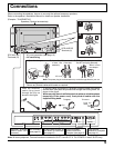
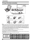
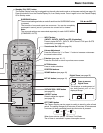
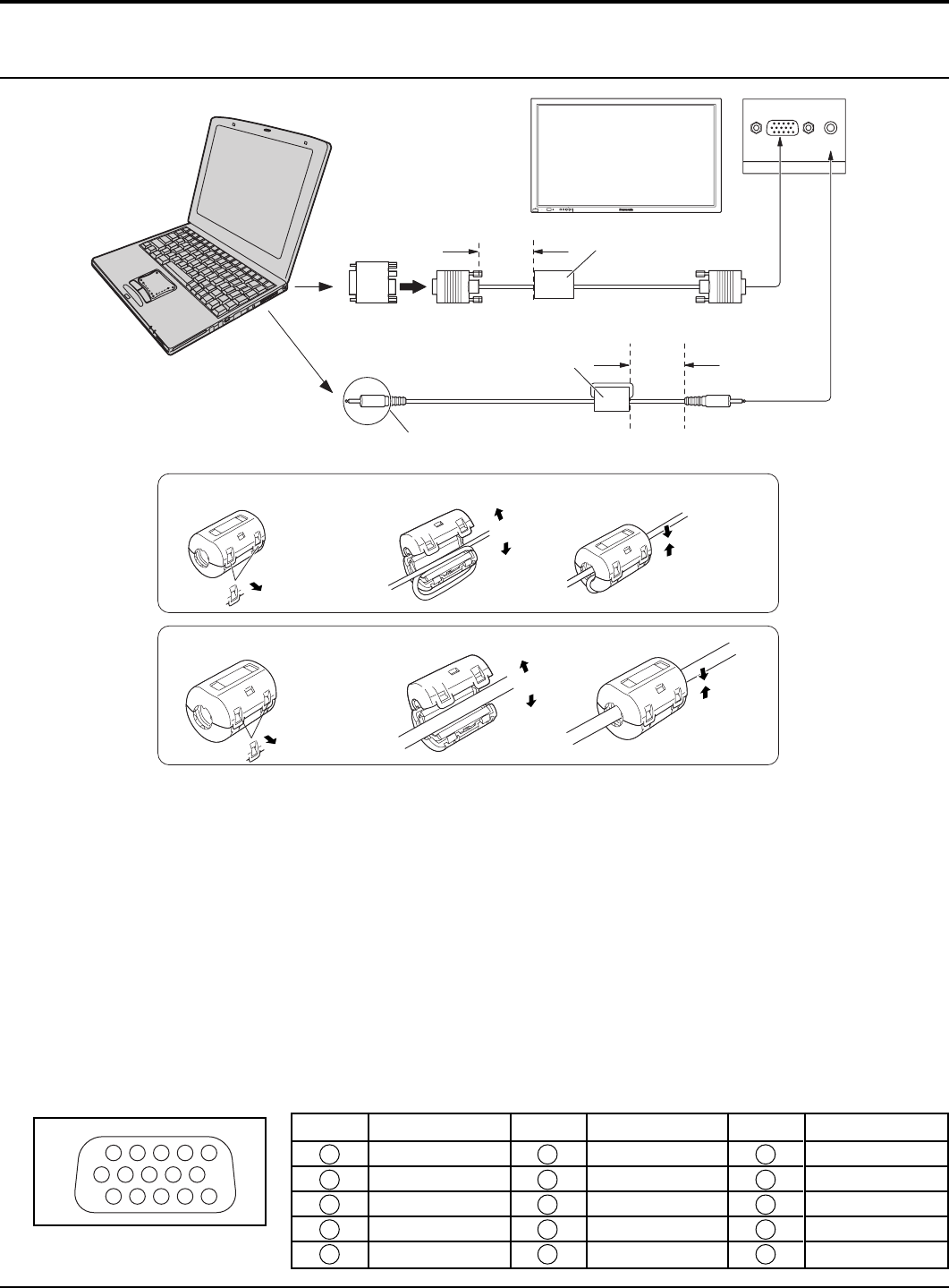
PC Input Terminals connection
Notes:
• Computer signals which can be input are those with a horizontal scanning frequency of 15 to 110 kHz and vertical
scanning frequency of 48 to 120 Hz. (However, the image will not be displayed properly if the signals exceed 1,200 lines.)
• The display resolution is a maximum of 640 × 480 dots (TH-37PWD7UY, TH-42PWD7UY), 768 × 768 dots (TH-42PHD7UY),
1,024 × 768 dots (TH-50PHD7UY) when the aspect mode is set to “NORMAL”, and 852 × 480 dots (TH-37PWD7UY, TH-
42PWD7UY), 1,024 × 768 dots (TH-42PHD7UY), 1,366 × 768 dots (TH-50PHD7UY) when the aspect mode is set to
“FULL”. If the display resolution exceeds these maximums, it may not be possible to show fine detail with sufficient clarity.
• The PC input terminals are DDC1/2B-compatible. If the computer being connected is not DDC1/2B-compatible, you will
need to make setting changes to the computer at the time of connection.
• Some PC models cannot be connected to the set.
• There is no need to use an adapter for computers with DOS/V compatible D-sub 15P terminal.
• The computer shown in the illustration is for example purposes only.
• Additional equipment and cables shown are not supplied with this set.
• Do not set the horizontal and vertical scanning frequencies for PC signals which are above or below the specified
frequency range.
• Component Input is possible with the pin 1,2,3 of the D-sub 15P Connector.
AUDIO
PC IN
COMPUTER
Conversion adapter
(if necessary)
RGB
D-sub 15p
Stereo plug
PC cable
Connect a cable which matches
the audio output terminal on the computer.
Less than
3"
15
/
16
(10 cm)
Ferrite core (small size)
(supplied)
Ferrite core (large size)
(supplied)
Audio
Less than
3"
15
/
16
(10 cm)
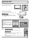
R - STANDBY
G POWER ON
INPUTMENU ENTER
–+
VOL
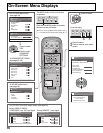
Installing the ferrite core (Small size)
Pull back the tabs
(in two places)
Open
Press the cable
through and close
1
2
3
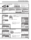
Installing the ferrite core (Large size)
Pull back the tabs
(in two places)
Open
Press the cable
through and close
1
2
3
1
678
3
9
45
10
1514131211
2
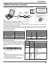
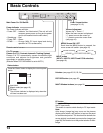
Signal Names for D-sub 15P Connector
Pin Layout for PC Input Terminal
Pin No.
1
2
3
4
5
Pin No.
6
7
8
9
10
Pin No.
11
12
13
14
15
Signal Name
R (P
R
/C
R
)
G(Y)
B(P
B
/C
B
)
GND (Ground)
GND (Ground)
Signal Name
GND (Ground)
GND (Ground)
GND (Ground)
NC (not connected)
GND (Ground)
Signal Name
GND (Ground)
SDA
HD/SYNC
VD
SCL
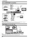
Connections