


8 z
OPTIONAL EQUIPMENT CONNECTIONS
ENGLISH
Optional Equipment Connections (cont.)
VCR and Cable Box Connection (Cont.)
Recording a premium (scrambled) cable channel
Procedure
• Select ANT2 in the SET UP menu.
• Press the TV/VIDEO button on the remote control to
select the video input (VIDEO 1, VIDEO 2, etc.)
connected to your VCR.
• Turn the VCR ON.
• Tune the VCR to Channel 3 or 4, depending on the
switch setting on the back of VCR.
• Using your cable box, tune to the premium cable channel
you want to record.
• Begin recording.
To view a different channel while recording:
• Select ANT1 in the SET UP menu.
• Press the TV/VIDEO button on the remote control to TV
mode.
• Tune the television to a program (except another
premium cable channel).
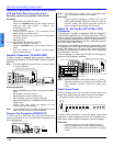
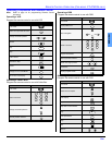
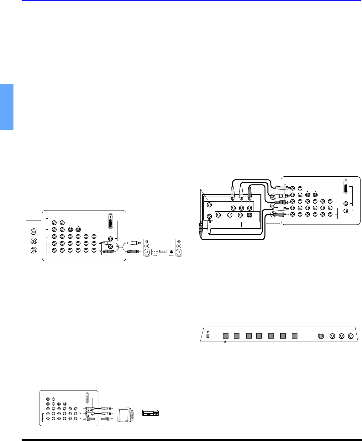
Amplifier Connection (TO AUDIO AMP)
To listen through a separate stereo system, connect an
external audio amplifier TO AUDIO AMP outputs on back of
television.
Note: TO AUDIO AMP terminals cannot be connected directly
to external speakers.
Audio Adjustments
• Select SPEAKERS ON located in the onscreen AUDIO
menu.
• Set amplifier volume to minimum.
• Adjust television volume to desired level.
• Adjust amplifier volume to match the television.
• Select SPEAKERS OFF & VARIABLE AUDIO OUT from
AUDIO menu.
• Volume, mute, bass, treble and balance are now
controlled through the television.
Note: Select SPEAKERS OFF & FIXED AUDIO OUT to control
audio functions through the external amplifier.
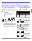
Program Out Connection (PROG OUT)
To use the television audio and video with optional equipment,
connect the PROG OUT and TO AUDIO AMP connections on the
back of the television.
Note: If the main picture signal is DVI or Component video
input, no Program Out function is available.
Procedure
• Connect optional equipment to PROG OUT and TO
AUDIO AMP terminals. PROG OUT display is same as
onscreen display. See optional equipment manual for
further instructions for recording and monitoring.
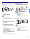
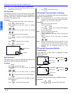
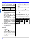
Digital TV - Set-Top Box (DTV-STB) or DVD
Connection
This television is capable of displaying 1080i and 480p DTV
signals when connected to a DTV tuner set-top-box (STB). In
order to view DTV programming, the STB must be connected
to the component video inputs (Y,PB,PR) of the television. A
DTV signal must be available in your area. Select the output of
the STB to either 1080i or 480p.
This television also utilizes a progressive scan doubler, which
de-interlaces the NTSC signal and progressively scans the
image. This allows you to sit close to the TV and not see the
thin black horizontal lines (venetian blind effect) associated
with interlaced TV pictures.
Use this diagram to connect the DTV-STB or DVD player to
the back of your projection television.
Note: There are two sets of three video iacks, Y, P
B
, and P
R
.
Separate component color inputs provide luminance and
color separation. Use the L (left) and R (right) audio
inputs.
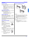
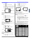
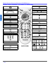
Front Control Panel
The front control panel can be used to access menus and
switch video mode when the remote control is not available.
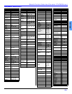
A second VCR, Camcorder, a video disc player, video game
equipment or DSS equipment can also be connected to the
video inputs. See the optional equipment manual for details
.
Procedure
• Connect equipment to front Audio/Video input jacks.
• Press TV/VIDEO button to select VIDEO 4 input mode.
• Operate optional equipment as instructed in equipment
manual.
CABLES NOT SUPPLIED
EXTERNAL AMPLIFIER
S-VIDEO
COMPONENT
VIDEO INPUT
VIDEO
1
2
INPUT
1
INPUT
2
INPUT
3
PROG
OUT
TO AUDIO
AMP
L
R
AUDIO
VIDEO
Y
P
B
P
R
L
R
AUDIO
DIGITAL
IN
ANT 1
SPLIT OUT
ANT 2
TERMINALS ON BACK OF PROJECTION TELEVISION
L
R
CABLES NOT SUPPLIED
S-VIDEO
COMPONENT
VIDEO INPUT
VIDEO
1
2
INPUT
1
INPUT
2
INPUT
3
PROG
OUT
TO AUDIO
AMP
L
R
AUDIO
VIDEO
Y
P
B
P
R
L
R
AUDIO
DIGITAL
IN
TERMINALS ON BACK OR PROJECTION TELEVISION
L
R
VCR
OR
MONITOR
CABLES NOT SUPPLIED
TERMINALS ON BACK OF DTV-STB OR DVD PLAYER
R-AUDIO-L - VIDEO S-VIDEO
NTSC OUTPUT
Y
P
B
P
R
MAIN
VIDEO
DIGITAL TV OUTPUT
L-AUDIO-R
S-VIDEO
COMPONENT
VIDEO INPUT
VIDEO
1
2
INPUT
1
INPUT
2
INPUT
3
PROG
OUT
TO AUDIO
AMP
L
R
AUDIO
VIDEO
Y
P
B
P
R
L
R
AUDIO
DIGITAL
IN
ANT 1
SPLIT OUT
ANT 2
TERMINALS ON BACK OF PROJECTION TELEVISION
L
R
POWER VOLUME CHANNEL ACTION TV/VIDEO S-VIDEO VIDEO 4 L - AUDIO - R
ON/OFF
INDICATOR
POWER ON/OFF
The ON/OFF indicator LED (red) will be lit when set is on.