


SLOT2
AUDIO
DVI-D IN
SLOT3
P
R
/C
R
/R P
B
/C
B
/B
Y/G
AUDIO
R L
COMPONENT/RGB IN
AUDIO
OUT
Y , P
B , P R ,
OUT
P
R
P B
Y
L
R
COMPONEN T VIDEO OUT
11
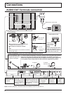
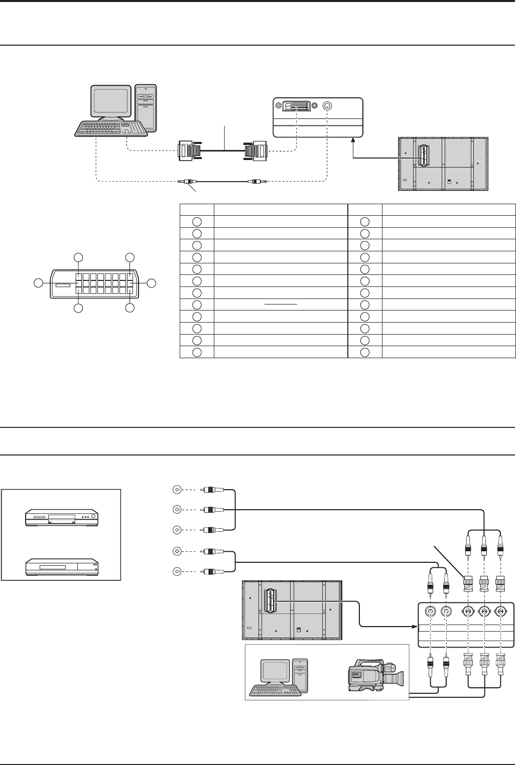
Connections
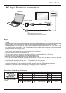
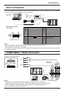
DVI-D connection
Mini-plug (M3)
DVI-D
video cable
(Within 5 m)
PC with DVI-D
video out
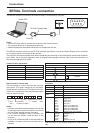
Pin No.
Signal Name
Pin No.
Signal Name
1
T.M.D.S. data 2-
13
T.M.D.S. data 3+
2
T.M.D.S. data 2+
14
+5 V DC
3
T.M.D.S. data 2/4 shielded
15
Ground
4
T.M.D.S. data 4-
16
Hot plug sense
5
T.M.D.S. data 4+
17
T.M.D.S. data 0-
6
DDC clock
18
T.M.D.S. data 0+
7
DDC data
19
T.M.D.S. data 0/5 shielded
8
20
T.M.D.S. data 5-
9
T.M.D.S. data 1-
21
T.M.D.S. data 5+
10
T.M.D.S. data 1+
22
T.M.D.S. clock shield
11
T.M.D.S. data 1/3 shielded
23
T.M.D.S. clock+
12
T.M.D.S. data 3-
24
T.M.D.S. clock-
Notes:
• Additional equipment, cables and adapter plugs shown are not supplied with this set.
• Refer to page 51 for applicable input signal.
• Use the DVI-D cable complying with the DVI standard. Image deterioration may occur depending on the length or
the quality of the cable.
DVI-D Input Connector
Pin Layouts
Connection port view
16
17
24
8
1
9
COMPONENT / RGB connection
Notes:
• Change the “Component/RGB-in select” setting in the “Setup” menu to “Component”
(when Component signal connection) or “RGB” (when RGB signal connection). (see page 39)
• Additional equipment, cables and adapter plugs shown are not supplied with this set.
• Sync on G signal is needed. (see page 42)
RCA-BNC
adapter plug
Computer
RGB Camcorder
or
DVD
Example of input signal source
Digital TV-SET-TOP-BOX
(DTV-STB)
This unit has terminal boards equivalent to DVI-D Terminal Board for PF Series (TY-FB9FDD) and BNC Component
Video Terminal Board (TY-42TM6A) as standard equipment.