16
Video Signal Path Explanation
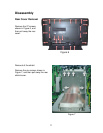
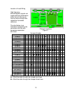
HY/HZ Board
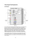
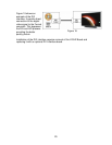
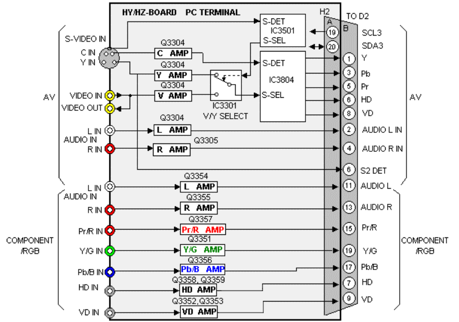
Figure 13
The "HY/ HZ" board is equipped with one Component input, one Composite input
and one S-Video input. The Composite and S-Video inputs are applied to a
switching circuit, which is controlled by the system control IC, located on the D1-
Board. The switch select command is sent via the SCL3 and SDA3 lines. After
signal selection the composite or S-Video signals are amplified, buffered, and
applied to a 3D comb filter inside IC3803. The 3D Comb filter converts the
Composite input signals to Y, Pb, and Pr component signals. The output of
IC3804 is applied to the D1 Board via pins 1, 3, and 5 of the connector H2/D2.
Individual amplifiers buffered the Component input signals that are then applied
to the D1-Board via pins 15, 17, and 19 of the connector H2/D2. Vertical and
Horizontal Sync signals are also amplified on this board before they are applied
to the D1 Board.


