


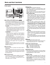


11
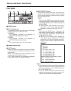
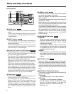
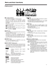
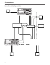
Display panel
1TV system displays
The selected TV system is displayed here.
With the AJ-SD955B, it is possible to switch
between the 525 interlace and 625 interlace
systems by setting setup menu item No. 070 (TV
SYSTEM).
With the AJ-SD930B, only the 525 interlace TV
system can be used.
: This lights when the 525 interlaced TV system
has been selected.
: This lights when the 625 interlaced TV system
is selected.
2WIDE lamp
This lamp lights when 16:9 wide-screen information
is being recorded on a tape.
Recording of wide-screen information can be
selected on setup menu No. 645 (WIDE SELECT).
This lights lamps during tape playback when wide-
screen information has been recorded on the tape.
3REMOTE lamp
This lamp lights when the CONTROL switch has
been set to the REMOTE position.
4INPUT SELECT display area
The characters corresponding to the selected input
signals light. With all input signals except for analog
audio signals, the fact that no signals have been
selected is indicated by a flashing display.
Y PB PR :
Analog component video signals
(option)
CMPST :
Analog composite video signals
(option)
SDI :
Serial digital video signals
SDTI/1394 :
Compressed digital signals (option)
SG/SG 1/SG 2:
Internal reference signals
ANALOG :
Analog audio signals
AES/EBU :
Digital audio signals
USER SET :
Recording audio signal selection
SDI :
Serial digital audio signals
SDTI/1394 :
Compressed digital signals (option)
SG :
Internal reference signals
AUDIO
VIDEO
SD955B
625
525
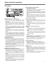
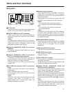
Parts and their functions
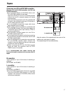
3 6 8
5
741 92
CTL
ANALOG
AUDIO
U
AES/EBU
USER SET
SDI
SDTI/1394
SG
INH
SCH
DVCPRO
50
DVCAM
SERVO
EDIT REC
TC
UB
=
Y PB PR
VIDEO
CMPST
SDI
SDTI/1394
SG 1 2
REMOTEWIDE
625525
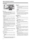
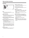
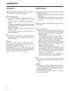
dB
0
-
4
-
8
-
12
-
16
-
20
-
25
-
30
-
L R
dB
0
-
4
-
8
-
12
-
16
-
20
-
25
-
30
-
L R
dB
0
-
4
-
8
-
12
-
16
-
20
-
25
-
30
-
L R
dB
0
-
4
-
8
-
12
-
16
-
20
-
25
-
30
-
L R
dB
CUE
-
8
-
12
-
16
-
20
-
25
-
30
-
L R
5 lamp
This lamp lights when UMID information is present
on the input signal in E-E mode.
This lamp lights during tape playback when UMID
information has been recorded on the tape.
6SCH lamp
This lamp lights when the SCH phase of the
external synchronized signal (REF VIDEO) is inside
the prescribed range.
At all other times, the lamp is off.
7
=
lamp
This lamp lights when a cassette tape is inserted
into the VTR.
In the standby OFF mode, this lamp is flashing.
8SERVO lamp
This lamp lights when the drum servo or capstan
servo locks.
9Channel condition lamps
These lamps light to indicate the error rate status.
(green 5 white 5 red)
Green:
This lights when the error rates for the video
and audio playback signals are both at
acceptable levels.
White :
This lights when the error rate for the video
or audio playback level has increased.
The playback picture and sound remain
unaffected even while this lamp is lighted.
Red :
This lights when the error rate for the video
or audio playback level has increased to the
extent that correction or interpolation was
performed.
U