


– 14 –
Controls and their functions
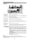
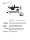
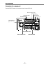
Connector section
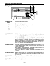
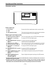
Power supply part
(1) AC IN socket Connect this with the supplied power cable to a power outlet.
(2) FUSE
(3) GND (ground) terminal This terminal serves to reduce the noise when external peripher-
al units are connected. This is not a safety earth.
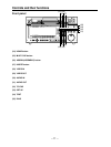
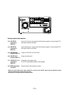
Digital signal input/output section
(4) SD SDI IN connectors (BNCt2) This is an active through input for SD SDI serial digital signals.
(5) SD SDI OUT1, 2 connectors For output of SD SDI serial digital signals.
(BNCt2)
(6) SD SDI MONITOR OUT connector For output of SD SDI serial digital signals.
(BNCt1) The time code can be superimposed.
(7) SPARE connector (BNCt1) This is a spare connector to which no component is connected.
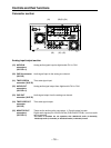
(8) HD SDI IN connectors (BNCt2) This is an active through input for HD SDI serial digital signals.
(9) HD SDI OUT1, 2, 3 connectors For output of HD SDI serial digital signals.
(BNCt3)
(10) HD SDI MONITOR OUT connector For output of HD SDI serial digital signals.
(BNCt1) The time code can be superimposed.
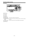
(11) DIGITAL AUDIO IN CH1/2, CH3/4 Input of digital audio signals according to the AES standard.
(CH5/6, CH7/8)°
1
connectors
(BNCt4)
(12) DIGITAL AUDIO OUT CH1/2, Output of digital audio signals according to the AES standard.
CH3/4 (CH5/6, CH7/8)°
2
connectors (BNCt4)
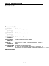
°
1
The items in brackets are not operative with 1080/59.94i audio (4 channels), 720/59.94p audio (4 channels) or
480/59.94i audio (4 channels) format.
°
2
A function is provided to copy the sound of channels 1 through 4 onto channels 5 through 8 when the
1080/59.94i audio (4 channels), 720/59.94p audio (4 channels) or 480/59i audio (4 channels) format is used. For
further details, refer to the AUDIO OUT SET UP menu in the operating instructions for the software.
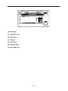
CH 1 CH 2 CH 3 CH 4
CH 1 CH 2 CH 3 CH 4
CUE
CUE
LR
OUT