– 15 –
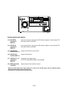
Analog input/output section
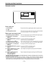
(13) HD REF IN Input of tri-level sync signals as the HD reference signals. A loop-through/75 ≠
connectors termination switch is provided.
(BNCt2)
(14) SD REF IN Input of black burst°
1
signals as the SD reference signals. A loop-through/75 ≠
connectors termination switch is provided.
(BNCt2)
(15) HD REF OUT Output of HD SYNC (tri-level SYNC).
terminal (BNCt1)
(16) SD REF OUT Output of black burst°
2
.
terminal (BNCt1)
(17) VIDEO OUT1, 2, 3 Composite video signal output.
connectors For OUT3, superimpose output is also possible.
(BNCt3)
(18) WFM (waveform) Signals output to the waveform monitor.
connector
°
1
When the normal black burst signal (59.94 Hz) is input as the SD REF signal with the 1080/24p system,
asynchronization and a picture error will result.
°
2
This signal is not output with the 1080/24p system.


