


26
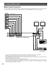
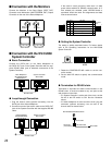
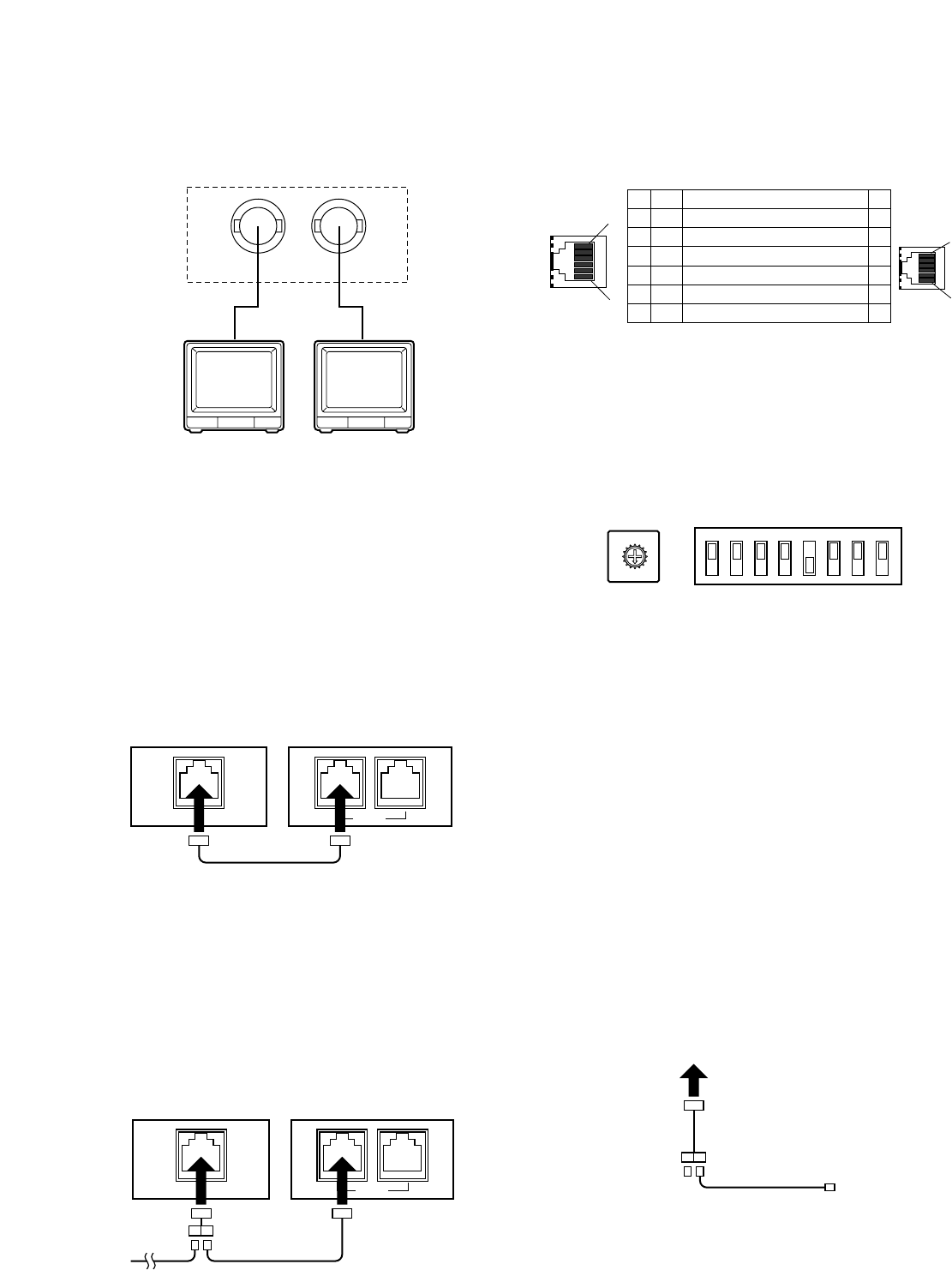
■ Connection with the WV-CU360
System Controller
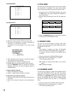
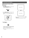
● Basic Connection
Connect the DATA jack on the Video Multiplexer to
the DATA OUT jack on the System Controller with the sup-
plied RS-485 cable (part of standard accessories of the
System Controller).
● Loop-through Connection
1. Plug the branch cable (optional accessory) into the
DATA jack of the Video Multiplexer.
2. Connect one end of the branch cable to the DATA OUT
jack on the System Controller with the supplied RS-485
cable.
DATA
Video Multiplexer
WJ-FS309/FS409/
FS316/FS416
RS-485 Cable
System Controller
WV-CU360
DATA
DATA
System Controller
WV-CU360
DATA
Video Multiplexer
WJ-FS309/FS409/
FS316/FS416
RS-485 Cable
Branch Cable
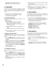
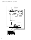
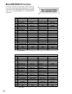
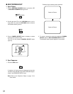
If the cable is locally procured, make sure it is data
grade cable suitable for RS-485 communication. A 2-
wire twisted pair shielded cable, BELDEN 9406 or
equivalent should be used. Pin assignments and data
flow are shown below.
1
6
1
6
No. No.
Name
Data Flow
11
GND
–
22
RX(B)
WJ-FS309/FS316/FS409/FS416 ← WV-CU360
33
RX(A)
WJ-FS309/FS316/FS409/FS416 ← WV-CU360
44
TX(B)
WJ-FS309/FS316/FS409/FS416 → WV-CU360
55
TX(A)
WJ-FS309/FS316/FS409/FS416 → WV-CU360
66
GND
–
Controller
end
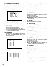
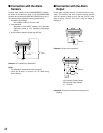
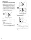
● Setting the System Controller
The setting is briefly described below. For further details
refer to the Operating Instructions for the WV-CU360
System Controller.
0
9
8
7
6
5
4
3
2
1
CONTROLLER No.
MODE
12345678
OFF
ON
1. Rotate the CONTROLLER NO. switch to set the con-
troller number.
2. Set the 8-bit DIP switch to specify the communication
mode.
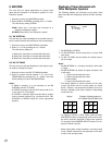
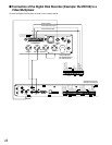
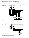
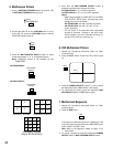
■ Connection with the Monitors
Connect the Monitors to the Spot Output (SPOT OUT)
Connector and Multiscreen (MULTISCREEN OUT) Output
Connector on the rear of the Video Multiplexer.
Video Monitor Video Monitor
SPOT OUT
MULTI
SCREEN OUT
WJ-FS309/FS409/FS316/FS416
Branch Cable
RS-485 Cable
WV-CU360
Terminator
(If necessary)
● Termination for RS-485 chain
Termination is important for stable communications in the
RS-485 chain. It must be located at only one point at the
end positions in the chain.
• If a System Controller is at the end of the chain, set the
5th bit of the DIP switch to ON. See the illustration
above.
• If a Video Multiplexer is at the end of the chain, plug the
terminator (optional accessory) into one end of the
branch cable as shown below.