


28
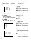
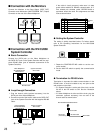
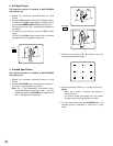
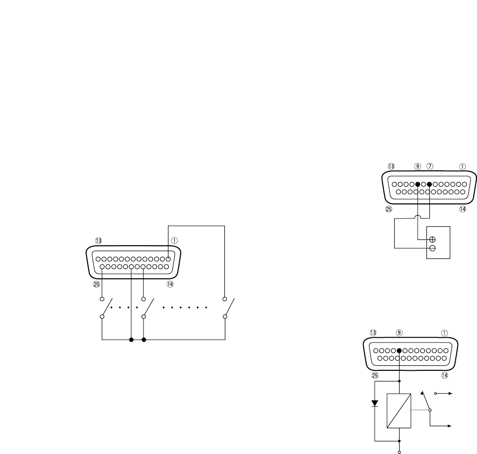
Example: N.O. specified by ALM INPUT
Notes:
• For detailed pin assignments refer to page 27.
• Leave pin #5 open, or connect it to +5 V when using
Alarm Sensors.
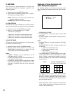
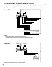
■ Connection with the Alarm
Output
Pin #9 (open collector) turns to 0 V while the alarm is acti-
vated. This terminal can drive external warning devices
such as a buzzer or lamp of up to 100 mA, 24 V DC. If the
rating exceeds 100 mA, 24 V use a relay as shown in
Example 2.
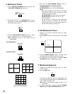
Example 1: Direct drive connection
Example 2: Connection of devices exceeding drive
capacity
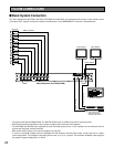
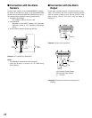
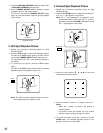
■ Connection with the Alarm
Sensors
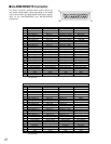
Connect alarm sensors to the ALARM/REMOTE connector.
As shown in the tables on page 27, the WJ-FS309/FS409
accepts up to 9 sensors and the WJ-FS316/FS416 up to 16.
The sensors should meet the following specifications:
1. Allowable input voltage:
Non-voltage contact, or 0 V to 5 V DC
2. Input definition:
Specified by ALM INPUT settings, N.O. (Normally
Open/Low active) or N.C. (Normally Closed/High
active)
3. Active duration: Must be longer than 250 ms.
Sensor 8
GND
Alarm
Sensor 1
Alarm
Sensor 16
Buzzer
NO
C
NC
To Buzzer
Relay
+24V
NC: Normally Closed Contact
NO: Normally Open Contact
C: Common