40
Data format
Format
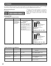
(Send 1) 5 channel: Alarm mode
[sfx]ADOOA; ALM:[OF][OF][OF]
[OF][B7][OF][efx]
(Response) None
5ch: Alarm mode
b
1
b
2
b
3
a
1
a
2
a
3
a
4
0Fh 0Fh 0Fh 0Fh 87h 0Fh 0Fh
5ch, 15ch, 16ch: Alarm mode
b
1
b
2
b
3
a
1
a
2
a
3
a
4
0Fh 0Fh 0Fh 0Fh 87h 0Fh 3ch
17ch: Alarm mode
b
1
b
2
b
3
a
1
a
2
a
3
a
4
0Fh 0Fh 1Eh 87h 0Fh 0Fh 0Fh
128ch: Alarm mode
b
1
b
2
b
3
a
1
a
2
a
3
a
4
0Fh 0Fh 78h 0Fh 0Fh 0Fh 1Eh
APPENDIX
This appendix details the elements for communication between the Video Multiplexers and the System Controller. For BAUD
RATE, DATA BIT, PARITY CHECK, STOP BIT and WAIT TIME, see page 20 COMMUNICATION SETUP menu.
uuu=001 to 099 (Unit address)
● Communication Protocol
Data Format
A message consists of [STX], [Address], [;], [Command],
[;], [Parameter], and [ETX]. [Address] is expressed as
[Aduuu] where uuu is in the range of 001 through 099 in
decimal form to identify the unit number of the Video
Multiplexer.
Notice of alarm occurrence ALM: b
1
b
2
b
3
a
1
a
2
a
3
a
4
b
1
b
2
b
3
=Notice of
First Alarm Channel
a
1
a
2
a
3
a
4
=Notice of
Alarm Channel
b
n
Item Format Example
These notice messages will not be implemented if the ALARM DATA is set to OFF in the SETUP menu of the Video Multiplexer.
● Command Table
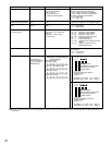
1. Video Multiplexer to System Controller
Code
[STX] [ADuuu][;] [Command][;] [Parameter] [EXT]
ASCII
(02H) ( ) ( ) ( ) ( ) ( ) (03H)
76543210
PPPPOOOO
Checking Code
Data that bit reversed notice
of First Alarm Channel
(3-digit number)
Bit Position
Notice of First Alarm Channel
(3-digit number)
Value: 0 - F
(Example 1) bn = 0001 1110 → Value: 1
(Example 2) bn = 0011 1100 → Value: 3
an
76543210
PPPPOOOO
Checking Code
Data that bit reversed notice
of First Alarm Channel
(3-digit number)
Bit Position
Notice of First Alarm Channel
(3-digit number)
Value: 0 - F
(Example 1) an = 0001 1110 → Value: 1
(Example 2) an = 0011 1100 → Value: 3
Single Spot Camera Select OCS : ccccc OCS : 00005 “ccccc” expresses a camera number.
ccccc = 00001 to 00128
Sequence activation OQT : 01F OQT : 01F
VCR/Camera select OVC : m OVC : 1 “m” denotes display mode selection.
m = 0: Camera mode
m = 1: VCR mode
Electronic Zoom OZM : + OZM : + Normal, Normal with + sign, x2 zoomed and
Normal are circulated.
Item Example Note/Parameter
2. System Controller to Video Multiplexer
Multi or Spot Select OMS : mmmm OMS : 0001 “mmmm” = 0001 Multi
= 0002 Spot


