


2.0 GENERAL INFORMATION
Thank you for your purchase of this Patton Electronics product.
This product has been thoroughly inspected and tested and is
warranted for One Year parts and labor. If any questions or problems
arise during installation or use of this product, please do not hesitate to
contact Patton Electronics Technical Support at (301) 975-1007.
2.1 FEATURES
• Converts parallel data to serial data or vice versa
• Automatically selects parallel-to-serial or serial-to-parallel operation
• Automatically selects DCE/DTE modes
• Serial data rates to 38,400 bps
• No AC power required
• Supports both software and hardware flow control
• A five-state LED monitors status and diagnostics
• External configuration switches
• Ultra-miniature size
• Made in the USA
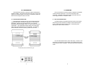
2.2 DESCRIPTION
The Patton Model 2026 and Model 2027 Parallel to Serial
Converters automatically convert RS-232 serial data to parallel data
format or vice versa. Incorporating advanced microprocessor
technology, they are able to automatically sense and select parallel and
serial modes, as well as DCE/DTE modes. Requiring no AC power, the
Model 2026 and 2027 support serial data rates to 38.4 Kbps.
For easy configuration, the Model 2026 and Model 2027 feature a
convenient set of external configuration switches. These accessible
configuration switches allow the user to control baud rate, parity, word
length and flow control. An easy-to-read LED indicator displays status
and operating condition.
Housed in an ultra-miniature ABS plastic case, the Model 2026
comes equipped with a DB-25 female or male connector on the serial
side and a Centronics 36 pin male connector on the parallel side. The
Model 2027 is housed in the same convenient case and comes
equipped with a DB-25 female connector on the serial side and male or
female connector on the parallel side.
3
APPENDIX B
PATTON MODEL 2026/2027 INTERFACE CONNECTIONS
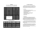
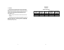
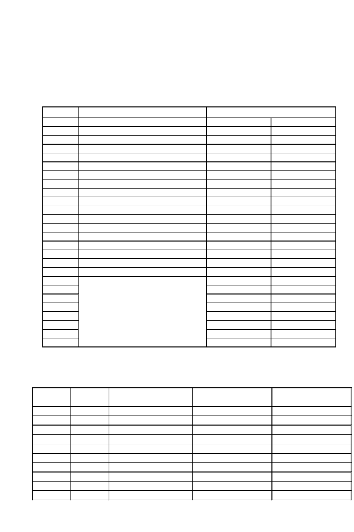
36 PIN CENTRONICS PARALLEL PORT CONNECTIONS
Note: All other pins are unconnected
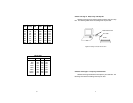
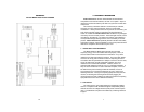
DB-25 PORT CONNECTIONS
Note: All other pins are unconnected
10
Pin Description Direction
Serial to Parallel Parallel to Serial
1 Strobe Output Input
2 Data Bit 0 Output Input
3 Data Bit 1 Output Input
4 Data Bit 2 Output Input
5 Data Bit 3 Output Input
6 Data Bit 4 Output Input
7 Data Bit 5 Output Input
8 Data Bit 6 Output Input
9 Data Bit 7 Output Input
10 Acknowledge Input Output
11 Busy Input Output
12 Paper End (to ground through resistor) Input Output
13 Select Input Output
14 To +5V through resistor
15 Error Input Output
16 To +5V through resistor
17 To +5V through resistor
18
19
20
21
22
23
24
25
Ground
Pin #
Signal
Name
Description
Connected to DTE Connected to DCE
1
FG
Frame Ground
2
TD
Transmit Data Input & Power Source Output
3
RD
Receive Data Output Input & Power Source
4
RTS
Request to Send Input & Power Source Output
5
CTS
Clear to Send Output Input & Power Source
6
DSR
Data Set Ready Output Input & Power Source
7
SG
Signal Ground
8
CD
Carrier Detect Output Input & Power Source
9
V+
External Power Source Input for Power Input for Power
20
DTR
Data Terminal Ready Input & Power Source Output