


5.0 OPERATION
Once your interface converter is properly configured and installed,
it should operate transparently—as if it were a standard cable
connection. Operating power is derived from the RS-232 data and
control signals; there is no “ON/OFF” switch.
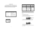
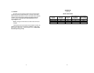
5.1 LED STATUS MONITORS
The Model 2026 and the Model 2027 feature easy-to-read status
LEDs that glow red to indicate the condition of the transmission line.
Figure 1 shows the location of these LEDs. The following chart
describes the LED’s various functions.
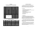
The red LED indicators blink to show data activity. However, since
there is only one indicator on each Model, it uses different LED codes
to demonstrate various messages. The following chart describes these
codes:
9
3.0 CONFIGURATION
The Model 2026 and 2027 are simple to install and designed for
excellent reliability. The following instructions will help you set up and
install your converter properly. If you have any questions, please call
Patton Technical Support at (301) 975-1007.
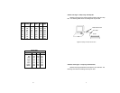
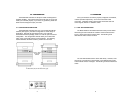
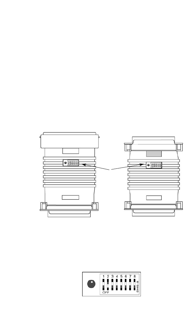
3.1 CONFIGURATION SWITCHES
The Model 2026 and 2027 each use a set of eight external DIP
switches (see Figure 1) that allow configuration to a wide range of
applications. Because all eight switches are in one externally
accessible DIP switch package, there is no need to open the case for
configuration. The configuration switches allow you to select data
rates, parity, word length and flow control selection. The following
section describes all switch locations, positions and functions.
4
Figure 1. The location of the configuration switches:
the Model 2026 (left) and the Model 2027 (right)
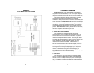
Figure 2. The miniature configuration switch package
Configuration
Switches