


9 of 9
ISSUED: 11-19-08 SHEET #: 120-9062-3 06-29-12
Visit the Peerless Web Site at www.peerless-av.com
For customer care call 1-800-865-2112.
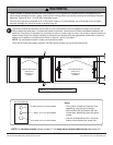
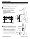
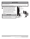
To attach screen to arm (not included), insert the puck of
adapter plate into the tilt bracket slot as shown in fi gure
3.1. Attach brake pad assembly as shown in Detail 3
so that the brake pad is snug against the adapter plate.
Adjust roll position of adapter plate to level screen then
lock puck in place by tightening M5 x 25 mm screw (B) on
the underside of tilt bracket using 4 mm allen wrench (I).
Tig
hten all (M5 x 20 mm, M5 x 25 mm) screws.
NOTE: To remove screen from arm, remove two
M5 x 20 mm screws (J) and brake pad. Lift screen out of
tilt bracket.
3
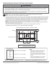
Installing and Removing Flat Panel Screen
• Do not lift more weight than you can handle. Use additional man power or mechanical lifting equipment to safely
handle placement of the screen.
• Failure to l
ock brake pad with two M5 x 20 mm screws (J) and lock tilt bracket with M5 x 25 mm screw (B) can
cause screen to come off mount if hit accidentally.
WARNING
fi g. 3.1
DETAIL 3
ADAPTER PLATE
BRAKE PAD
TILT
BRACKET
ARM
B
J
PUCK
• Do not tighten screws with excessive force. Overtightening
can cause damage to mount. Tighten M5 x 20 mm screws (J)
to 20 in. • lb (2.26 N.M.) maximum torque.
CAUTION
© 2012, Peerless Industries, Inc. All rights reserved.
All other brand and product names are trademarks or registered trademarks of their respective owners.