


3 of 6
ISSUED: 10-30-10 SHEET #:125-9164-1
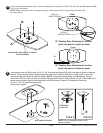
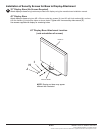
Hand tighten slope nut (D) through 1/4-20 x 1-3/4" thin head carriage bolt (C) until snug against bottom of desktop
surface. Thread another slope nut (D) upside-down, about two turns from rst slope nut (D). Insert an open box
wrench between both slope nuts (D) and tighten. NOTE: Avoid jamming both slope nuts (D) together, doing so
may make it difcult to remove slope nut used for tightening rst slope nut (D) as shown in g 4.1. After slope nut is
secure remove bottom slope nut and add plastic cap (E) as shown in gure 4.2. Repeat with remaining
1/4-20 x 1-3/4" thin head carriage bolt (C).
Skip to step 8 page 6.
Detail 1
TIGHTENING
SLOPE NUT
3
B
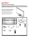
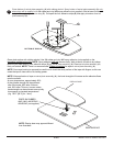
32" Display Base Attachment Location
(note orientation of plate to base)
BOTTOM OF DESKTOP
FIG 4.1 FIG 4.2
C
D
C
4
E
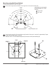
Secure swivel plate assembly (A) to bottom of display base using three 10-32 x 3/8" at head self drilling screws (B)
in 32" or 42" orientation.
NOTE: Make sure that screws in display base align with slots and holes in swivel plate assembly (A)
as shown below.
FRONT
NOTE: Do not overtighten slope nut (D)
plate may distort
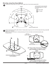
42" Display Base Attachment Location
(note orientation of plate to base)
A
ARROW INDICATES FRONT OF SWIVEL
PLATE ASSEMBLY
.88"
C
D
FRONT
DISPLAY
BASE SCREWS
DISPLAY
BASE SCREWS