7 of 36
ISSUED: 11-19-07 SHEET #: 202-9248-6 11-04-09
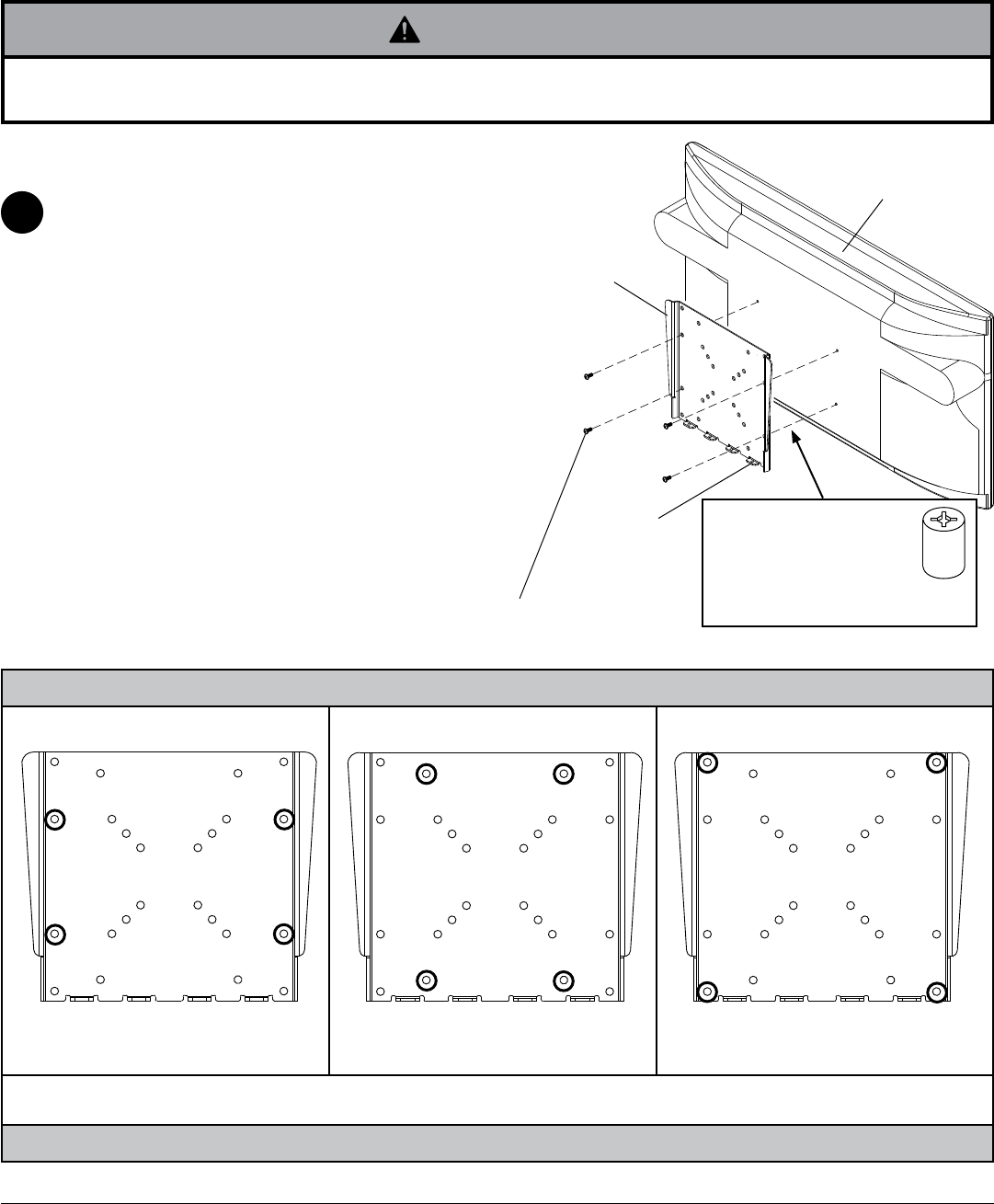
Attaching Mounting Plate to Screen with VESA
®
200 x 100, 120 x 180 or
200 x 200 Mounting Pattern
• If screws don't get three complete turns in the screen inserts or if screws bottom out and bracket is still not tightly
secured, damage may occur to screen or product may fail.
WARNING
FOR VESA
®
200 x 100, 120 x 180 or 200 x 200
MOUNTING PATTERN:
Choose hole pattern as shown in detail 2 for VESA
200 x 100, 120 x 180 or 200 x 200 mounting pattern
and for fasteners to use. Attach mounting plate (B) to
back of screen using four screws (F, G, J, K, or L) as
shown.
NOTE: Be certain bottom flanges of mounting plate
face toward bottom of screen.
*NOTE: If hole pattern is in a pocket, attach mounting
plate (B) to back of screen using four M4 x 20 mm
screws (G) and four retaining spacers (H) as indicated.
NOTE: If screw (J) gets less than three threads of
engagement, attach mounting plate (B) to back of
screen using four M6 x 20 mm screws (K). If screw (K)
still gets less than three threads of engagement, use
four M6 x 30 mm screws (L).
2
B
F, G , J, K or L
BOTTOM
FLANGES
Mounting Patterns
VESA
®
120 x 180 VESA
®
200 x 200VESA
®
200 x 100
DETAIL 2
SCREEN
M4 x 10 mm screws (F) or
M4 x 20 screws (G) with spacer (H)
M4 x 10 mm screws (F) or
M4 x 20 screws (G) with spacer (H)
M6 x 12 mm screws (J),
M6 x 20 mm screws (K) or
M6 x 30 mm screws (L)
NOTE: Fastener selection may vary for specific screens. If you have any questions for the correct fasteners to use for your
particular screen, call customer care.
H
*For screens with a
hole pattern in a pocket,
spacers (H) go between
mounting plate (B) and
screen when using
screws (G).


