


6 of 70
ISSUED: 10-30-09 SHEET #: 095-9299-11 03-22-12
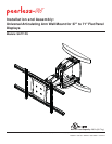
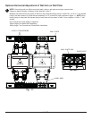
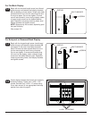
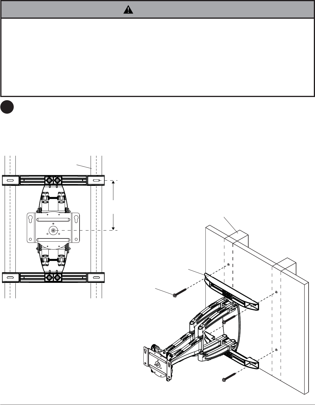
9"
(229 mm)
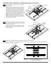
Use a stud fi nder to locate the edges of the studs and draw a vertical line down the center of each stud. Determine
and mark the desired display center on the wall. Place wall plate template (wall arm) on wall with top mounting slots
9" (229 mm) above desired display center as shown in fi gure 2.1. Level wall plate template (wall arm) on wall and
mark center of four mounting holes making sure that the mounting holes are on the stud centerlines. Drill four 3/16"
(5 mm) dia. pilot holes to a depth of 3" (76 mm). Attach wall arm (A) to wall using four wood screws (C) as shown in
fi g. 2.2.
Level wall plate then tighten all fasteners.
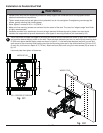
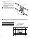
Installation to Double-Stud Wall
2
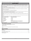
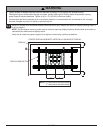
• Installer must verify that the supporting surface will safely support the combined load of the equipment and all
attached hardware and components.
• Tighten wood screws so that wall plate is fi rmly attached, but do not overtighten. Overtightening can damage the
screws, greatly reducing their holding power.
• Never tighten in excess of 80 in. • lb (9 N.M.).
• Make sure that mounting screws are anchored into the center of the stud. The use of an "edge to edge" stud fi nder
is highly recommended.
• Hardware provided is for attachment of mount through standard thickness drywall or plaster into wood studs.
Installers are responsible to provide hardware for other types of mounting situations (not evaluated by UL).
WARNING
C
A
WOOD STUD
WOOD STUD
fi g. 2.2
CS = CENTER OF DISPLAY
fi g. 2.1
CS