


9 of 70
ISSUED: 10-30-09 SHEET #: 095-9299-11 03-22-12
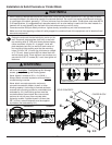
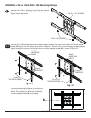
NOTE: If display has a VESA 400 horizontal
mounting pattern, skip to step 3-4 or 3-5 on page
11.
NOTE: For VESA 200x200 or VESA 200x100
mount hole patterns, skip to step 4 on page 12.
NOTE: For dedicated PLP plate installation skip to
step 5 on page 14.
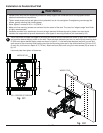
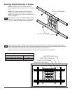
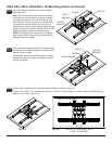
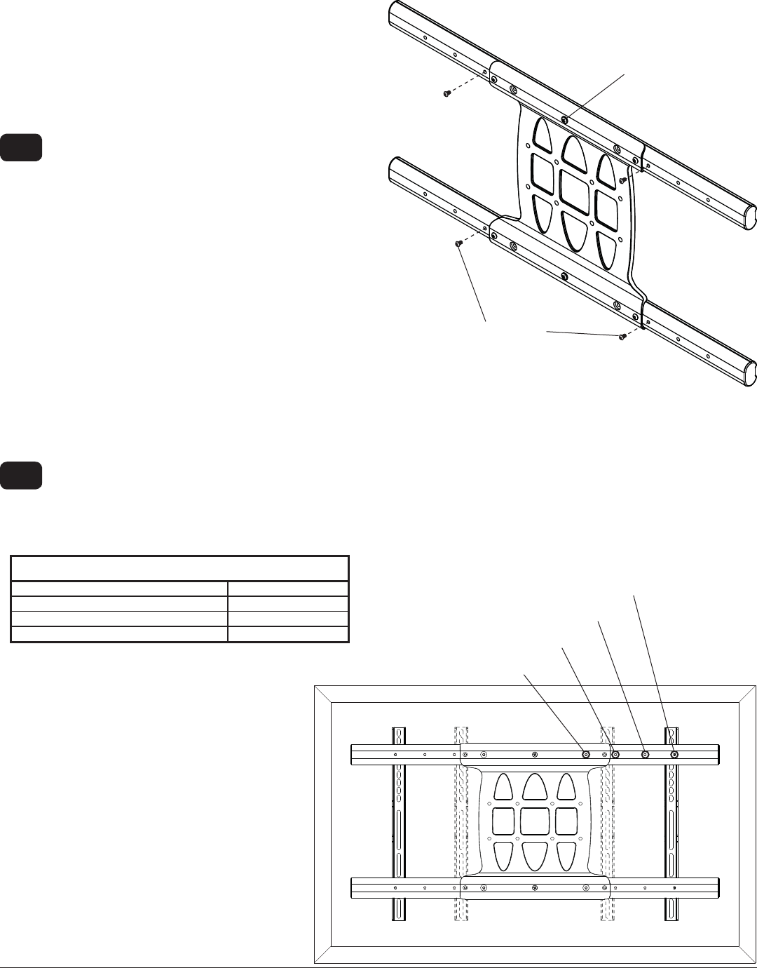
Remove four 1/4-20 x .6" screws using 5 mm allen
wrench (I) and loosen two 1/4-20 x 1.25" screws
1/2 turn to allow for display bracket adjustment.
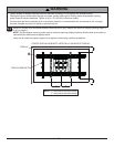
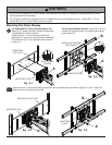
To prevent scratching the display, set a cloth on a fl at, level surface that will support the weight of the display.
Place display face side down and refer to display manufacturers instructions for removing obstructions from the
back of the display. Adjust display brackets to align with display mounting holes.
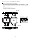
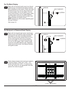
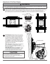
Measure horizontal mounting hole pattern and choose fi xed stop-position from chart below.
3-2
3-1
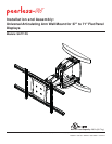
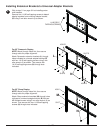
Installing Adapter Brackets to Display
FIXED STOP-POSTION #2
FIXED STOP-POSTION #1
FIXED STOP-POSTION #3
horizontal mounting hole pattern fixed stop-position
10-3/4" - 16-1/16" (273 - 408 mm) #1
15-1/16" - 21-9/16" (383 - 548 mm) #2
20-7/16" - 27-9/16" (519 - 700 mm) #3
26-1/16" - 32-9/16" (661 - 827 mm) #4
FIXED STOP-POSTION #4
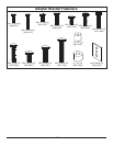
1/4-20 x .06" SCREWS
1/4-20 x 1.25" SCREWS