


4 of 6
ISSUED: 02-14-06 SHEET #: 202-9111-2 06-16-06
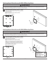
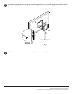
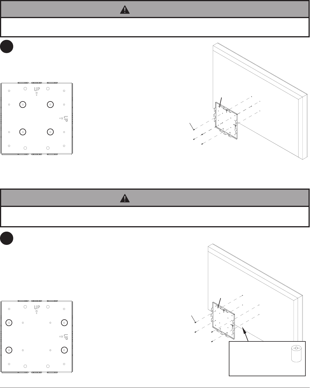
Choose hole pattern as shown in figure 2.2. Attach
adapter plate (B) to back of screen using four M4 x
10 mm screws (I) as shown.
Note: Orientation of "UP" arrow is critical.
*Note: If screw (I) gets less than three threads of
engagement, attach adapter plate (B) to back of
screen using four M4 x 20 mm screws (J) and four
spacers (K) as indicated below.
Skip to step 3 on page 6.
I
B
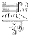
Attaching Adapter Plate to Screen with VESA 100 Mounting Pattern
2
• If screws don't get three complete turns in the screen inserts or if screws bottom out and adapter plate is still not
tightly secured, damage may occur to screen or product may fail.
WARNING
M
*For screens with a
hole pattern in a
pocket, spacers (K) go
between adapter plate
(B) and screen.
K
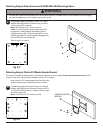
Attaching Adapter Plate to Screen with VESA 200 Mounting Pattern
• If screws don't get three complete turns in the screen inserts or if screws bottom out and adapter plate is still not
tightly secured, damage may occur to screen or product may fail.
WARNING
Choose hole pattern as shown in figure 2.1. Attach
adapter plate (B) to back of screen using four M4 x
10 mm screws (I).
Note: Orientation of "UP" arrow is critical.
Skip to step 3 on page 6.
2
fig 2.1
B
I
fig 2.2