


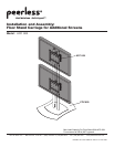
5 of 6
ISSUED: 02-14-06 SHEET #: 202-9111-2 06-16-06
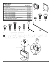
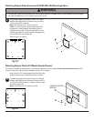
Choose hole pattern as shown in figure 2.3. Attach
adapter plate (B) to back of screen using four M6 x
12 mm screws (F) as shown.
Note: Orientation of "UP" arrow is critical.
*Note: If screw (F) gets less than three threads of
engagement, attach adapter plate (B) to back of
screen using four M6 x 20 mm screws (G). If screw
(G) still gets less than three threads of engagement,
use four M6 x 30 mm screws (H).
Skip to step 3 on page 6.
Attaching Adapter Plate to Screen with VESA 200 x 200 Mounting Pattern
• If screws don't get three complete turns in the screen inserts or if screws bottom out and bracket is still not tightly
secured, damage may occur to screen or product may fail.
WARNING
2
fig 2.3
B
F
E
4
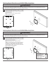
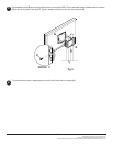
For screen compatibility please refer to the plasma interface list on our website www.peerlessmounts.com or call
customer care for a screen specific adapter bracket (PLP models).
GENERIC ADAPTER
BRACKET
Attaching Adapter Plate to PLP Model Adapter Bracket
fig 4.4
D
Note: Refer to PLP model adapter bracket instruction
sheet for attachment of adapter bracket to screen.
Choose hole pattern as shown in figure 4.4. Attach
adapter plate (D) to back of screen using four M10 x
15 mm screws (E) as shown. Tighten screws using 6
mm allen wrench (L).
Note: Orientation of "UP" arrow is critical.