


ISSUED: 09-09-02 SHEET #: 200-9432-12 07-14-05
Visit the Peerless Web Site at www.peerlessmounts.com For customer service call 1-800-729-0307 or 708-865-8870.
4 of 4
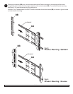
Slide the vertical brackets (BB) along the c-channels of the adapter bracket (AA) until the slots on the back of the
vertical brackets (BB) are aligned to the holes on the back of screen. Fully tighten the four 10-32 x 3/8" serrated
head socket pin screws (CC) which hold the vertical brackets (BB) to the c-channels. Refer to the accompanying
screen compatibility chart to determine the proper fasteners to use. Attach the assembled adapter bracket to the
back of the screen using screws, upper and lower spacers as pictured. Verify that all holes are properly aligned,
then use the security allen wrench (LL) to tighten the screws.
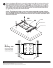
Note: See figure 5 below for slot sizes.
Example: For a Toshiba model 50 HP82 50" screen, attach the vertical brackets (BB) to the screen using eight
M4 x 10 mm serrated socket pin screws (GG) or M5 x 12 mm socket pin screws (FF) through the small slots on the
vertical brackets (BB). Please refer to the corresponding configuration note for more details. Upper spacers (JJ) are
required for this configuration.
3
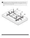
SCREWS
UPPER SPACERS
LOWER SPACERS
fig. 5
Mounting Slots
SMALL SLOTS ARE USED
FOR M4 AND M5 SCREWS.
LARGE SLOTS ARE USED
FOR M6 AND M8 SCREWS.
MOUNTING SLOTS: SMALL
MOUNTING SLOTS: LARGE
BB
C-CHANNNEL
AA
© 2004 Peerless Industries, Inc. All rights reserved.
Peerless is a registered trademark and Solid•Point is a trademark of Peerless Industries, Inc.
All other brand and product names are trademarks or registered trademarks of their respective owners.