


2 Pelco Manual C293M (11/98)
To install the SWM Series wall mount directly onto a wall, perform the following
steps (see Figure 1 and Table A):
1. Determine the location where the mount is to be installed.
2. Using the adjustment plate (supplied) as a template, drill holes into the mount-
ing surface.
3. Bring the electrical cables in from the cable hole in the mounting surface and
through the cable holes in the adjustment plate (if required) and mounting
cleat. Position the cleat so the elongated mounting fastener hole is below the
cable entry hole.
4. Fasten the adjustment plate (if used) and mounting cleat securely to the mount-
ing surface with two fasteners of appropriate length and size (not supplied). If
necessary, before tightening the two fasteners, insert shims between the ad-
justment plate and the mounting surface to achieve a perpendicular surface to
attach the wall mount. The lower hole in the mounting cleat is elongated, which
allows for vertical alignment adjustment.
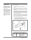
5. Feed the electrical cables through the mount, hook the mount onto the top of
the mounting cleat, and position the mount flush against the mounting sur-
face. Back out, if necessary, and tighten the set screw in the bottom of the
mount only until the mount is snug against the surface. Do not over-tighten
.
6. Attach the pendant dome back box to the mount:
a. Feed the electrical cables from the mount into the dome back box.
b. Apply anti-seize compound (supplied) to the dome back box pipe threads.
c. Screw the dome back box into the threads in the mount.
d. Complete the installation following the instructions in the dome manual.
3.0 INSTALLATION
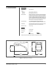
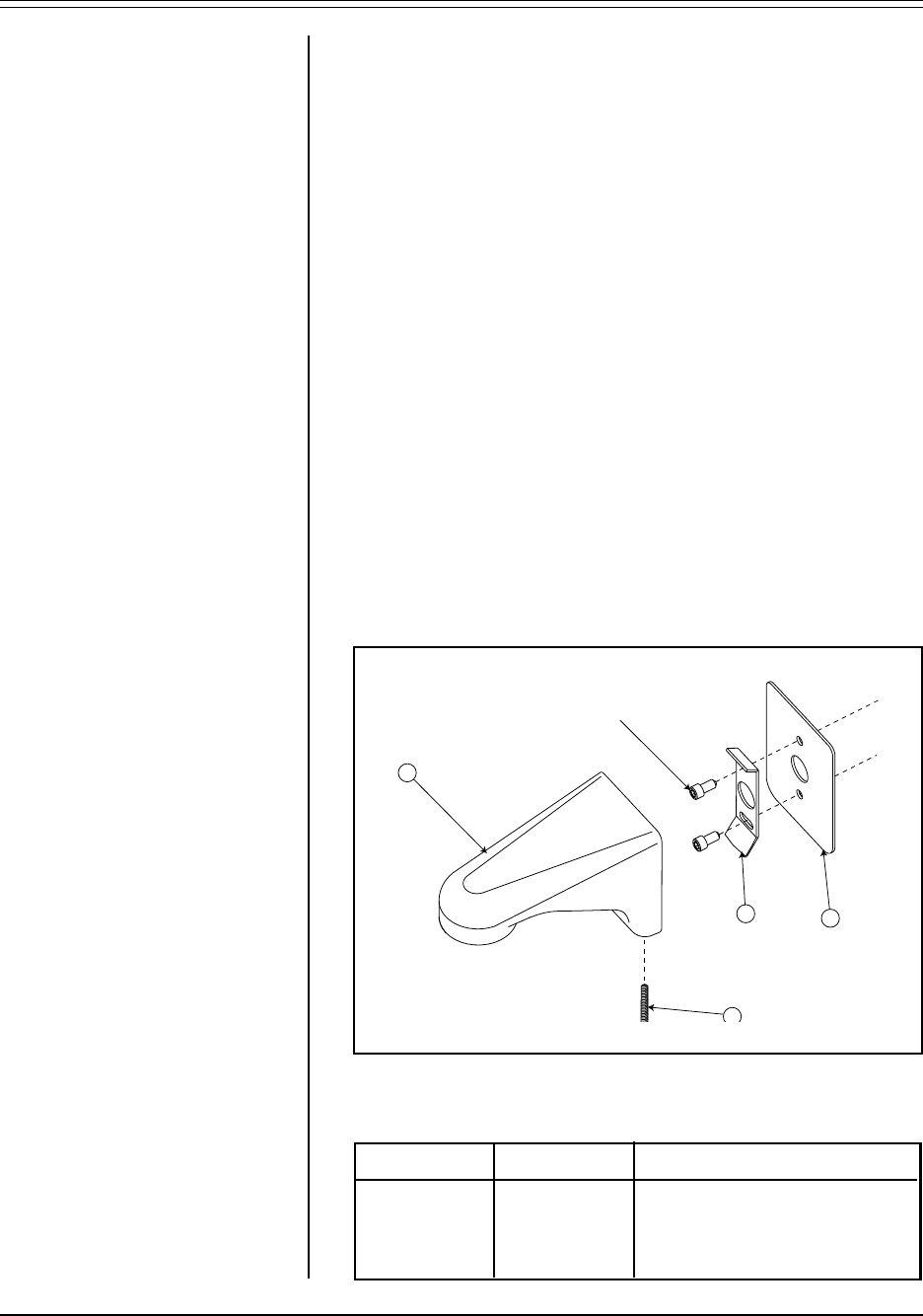
Item Qty Description
11Wall mount, gray or black
21Mounting cleat
31Set screw, 10-24
41Adjustment plate
Figure 1. SWM Spectra
®
Compact Wall Mount Locator Drawing
Table A. SWM Spectra
®
Compact Wall Mount Key List
NOTE:
The SWM Series wall
mount may also be attached to a
pole adapter. Refer to the SWM-
PA Series manual, C294M, for
mounting procedures.
NOTE:
An adjustment plate (item 4)
is provided to allow the wall mount
to be shimmed when the mounting
surface is not plumb. Use it as a
template for drilling holes in the
mounting surface before discard-
ing, if not required for shimming.
NOTE:
The mounting cleat has an
arrow embossed in it, for orienta-
tion purposes, and must point up-
ward.
MOUNTING FASTENERS
(NOT SUPPLIED)
1
3
2
4