C641M (11/03) 9
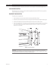
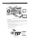
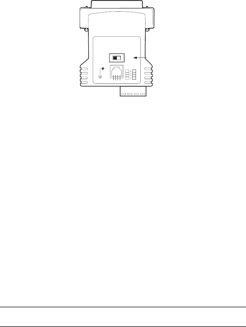
Figure 6. Bottom View of the RS-422 Converter
2 TCP/IP Access
Consult your network administrator to avoid possible network conflicts. For TCP/IP access, connect the DX7100 to a
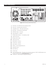
10/100 Ethernet network. Use a standard UTP Cat5 cable with RJ-45 connectors. Plug the cable into the LAN port located
on the back of the unit. Use a router with multicasting when connecting to a WAN network.
3 Analog Spot Monitor (Sequencing Only)
You can connect an analog monitor to the DX7100. This monitor is for viewing purposes only. Programming menus and
bars are not displayed on the screen. All enabled cameras are displayed on the monitor in a sequential order.
Connect the analog spot monitor to the output labeled VIDEO OUTPUT.
4 Sensor (Alarm) Inputs
The DX7100 has eight normally closed dry contact sensor inputs. Sensor inputs require an open circuit contact, such as a
switch or relay, to trigger an alarm.
To wire a sensor input:
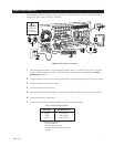
a. Connect one wire from the source device (for example, a door) to one of the sensor input terminals 1 through 8.
b. Connect a second wire from the source device to the COM terminal.
5 Relay Outputs (Maximum Power Rating 125 VAC, 0.5 A; 30VDC, 1 A)
The DX7100 has eight normally open dry contact relay outputs. A signal from a output will operate the device connected
to the output.
To wire a relay output:
a. Connect one wire from the device (for example, an alarm) to one of the relay output terminals 1 through 8.
b. Connect a second wire from the relay device to the COM terminal.
NOTE: The sensor input does not have to correspond numerically to the relay output. All sensor input and relay output actions
are linked through programming. Refer to the Operation/Programming manual for details.
Refer to the Operation/Programming manual for instructions on how to set up and operate the DX7100 DVR.
T+T-R-R+
DTE DCE
T+
T-
R-
R+
R+
R-
T-
T+
A B
Connection DC 9V
+
SET TO DC
E


